AKTAKOM AMM-1139 is a new Professional Digital Multimeter which provides much more safe measurements with double molded plastic housing design and IP67 waterproof function. AMM-1139 performs like datalogger & True RMS AC voltage and current measurements, 40,000 counts resolution and 0.06% basic DC accuracy for more customers. The large LCD display with analog bargraph and backlit ensures that all indcates are easy to read under all circumstances. All inputs are protected to EN 610101-1 CATIV 600V/CATIII 1000V.
Features:
- 40,000 counts high resolution (0.01mV, 0.01μA, 0.01Ω)
- Triple LCD display with bargraph & Backlit
- AC+DC Measurement
- 9999 Readings memories
- True RMS measurement & Peak capture mode
- 1000V input protection on all ranges
- 4-20mA process loop measurements with % reading
- Data Hold/MAX/MIN recording mode
- IP67 Waterproof and Auto Power Off
- Wide capacitance range
- Wireless USB interface
Safety Conformance
- EN61010-1 CAT IV 600V, CAT III 1000V
- 1000V input protection on all ranges
- 10A/1000V & 0.5A/1000V fuses protection on current ranges
Specifications
|
Function
|
Range
|
Resolution
|
Accuracy
|
|
DC Voltage
|
400mV
|
0.01mV
|
±(0.06%reading+4digits)
|
|
4V
|
0.0001V
|
|
40V
|
0.001V
|
|
400V
|
0.01V
|
|
1000V
|
0.1V
|
±(0.1%reading+3digits)
|
|
AC Voltage (AC+DC) 50 to 1000Hz
|
400mV
|
0.01 mV
|
±(1.0%reading+40digits)
|
|
4V
|
0.0001V
|
±(1.0%reading+30digits)
|
|
40V
|
0.001V
|
|
400V
|
0.01V
|
|
1000V
|
0.1V
|
|
All AC voltage ranges are specified from 5% of range to 100% of range
|
|
DC Current
|
400µA
|
0.01µA
|
±(1.0%reading+3digits)
|
|
4000µA
|
0.1µA
|
|
40mA
|
0.001mA
|
|
400mA
|
0.01mA
|
|
10A
|
0.001A
|
|
(20A:30s max with reduced accuracy)
|
|
AC Current (AC+DC) 50 to 1000Hz
|
400µA
|
0.01µA
|
±(1.0%reading+3digits)
|
|
4000µA
|
0.1µA
|
|
40mA
|
0.001mA
|
|
400mA
|
0.01mA
|
|
10A
|
0.001A
|
|
(20A: 30s max with reduced accuracy)
|
|
All AC voltage ranges are specified from 5% of range to 100% of range
|
NOTE: Accuracy is stated at 18°C to 28°C (65°F to 83°F) and less than 75%RH.
AC switch according to the calibration of sine wave. It generally increase ±(2% reading + 2% full scale) if non sine wave in the wave crest less than 3.0.
|
Function
|
Range
|
Resolution
|
Accuracy
|
|
Resistance
|
400Ω
|
0.01Ω
|
±(0.3%reading+9digits)
|
|
4kΩ
|
0.0001kΩ
|
±(0.3%reading+4digits)
|
|
40kΩ
|
0.001kΩ
|
|
400kΩ
|
0.01kΩ
|
|
4MΩ
|
0.001MΩ
|
|
40MΩ
|
0.001MΩ
|
±(2.0%reading+10digits)
|
|
Capacitance
|
40nF
|
0.001nF
|
±(3.5%reading+40digits)
|
|
400nF
|
0.01nF
|
|
4µF
|
0.0001µF
|
±(3.5%reading+10digits)
|
|
40µF
|
0.001µF
|
|
400µF
|
0.01µF
|
|
4000µF
|
0.1µF
|
±(5%reading+10digits)
|
|
40mF
|
0.001mF
|
|
Frequency (electronic)
|
40Hz
|
0.001Hz
|
±(0.1%reading+1digits)
|
|
400Hz
|
0.01Hz
|
|
4kHz
|
0.0001kHz
|
|
40kHz
|
0.001kHz
|
|
400kHz
|
0.01kHz
|
|
4MHz
|
0.0001MHz
|
|
40MHz
|
0.001MHz
|
|
100MHz
|
0.01MHz
|
Not specified
|
|
Sensitivity: 0.8V rms min. @ 20% to 80% duty cycle and <100kHz; 5Vrms min @ 20% to 80% duty cycle and > 100kHz.
|
|
Frequency (electrical)
|
40.00Hz-10kHz
|
0.01Hz-0.001kHz
|
±(0.5%reading)
|
|
Sensitivity: 1Vrms
|
|
Duty Cycle
|
0.1 to 99.90%
|
0.01%
|
±(1.2%reading+2digits)
|
|
Pulse width: 100µs-100ms, Frequency: 5Hz to 150kHz
|
|
Temperature (type-K)
|
-50 to 1200°C
|
0.1°C
|
±(1.0%reading+2.5°C) (probe accuracy not included)
|
|
-58 to 2192°F
|
0.1°F
|
±(1.0%reading+4.5°F) (probe accuracy not included)
|
|
4-20mA%
|
-25 to 125%
|
0.01%
|
>±50 digits
|
|
0mA=-25%, 4mA=0%, 20mA=100%, 24mA=125%
|
Note: Accuracy specifications consist of two elements:
- (%reading) — This is the accuracy of the measurement circuit.
- (+digits) — This is the accuracy of the analog to digital converter.
General specifications
Store capacitance: 9999
Enclosure: double molded, waterproof
Shock (Drop Test): 2M
Diode Test: test current of 0.9mA maximum, open circuit voltage 2.8V DC typical.
Continuity Check: audible signal will sound if the resistance is less than 35W (approx.), test current <0.35mA.
PEAK: captures peaks >1ms.
Temperature Sensor: requires type K thermocouple.
Input Impedance: >10MΩ VDC & >9MΩ VAC
AC Response: True rms
True RMS: The term stands for "Root-Mean-Square" which represents the method of calculation of the voltage or current value. Average responding multimeters are calibrated to read correctly only on sine waves and they will read inaccurately on non-sine wave or distorted signals. True rms meters read accurately on either type of signal.
ACV Bandwidth: 50Hz to 1000Hz
Crest Factor: <3 at full scale up to 500V, decreasing linearly to <1.5 at 1000V.
Display: 40,000 count backlit liquid crystal with bargraph.
Overrange indication: "OL" is displayed
Auto Power Off: 15 minutes (approximately) with disable feature
Polarity: automatic (no indication for positive); Minus (-) sign for negative
Measurement Rate: 2 times per second, nominal
Battery: One 9V (NEDA 1604) battery
Fuses: 0.5A/1000V ceramic fast blow (mA, µA ranges), 10A/1000V ceramic fast blow (A range)
Operating Temperature: 5°C to 40°C (41°F to 104°F)
Storage Temperature: -20°C to 60°C (-4°F to 140°F)
Operating Humidity: Max 80% up to 31 °C (87°F) decreasing linearly to 50% at 40°C (104°F)
Storage Humidity: <80%
Operating Altitude: 2000M maximum
Weight: 342g (includes holster)
Size: 187x81x50mm (includes holster)
Safety: This meter is intended for origin of installation use and protected, against the users, by double insulation per EN61010-1 and IEC61010-1 2nd Edition (2001) to Category IV 600V and Category III 1000V; Pollution Degree 2. The meter also meets UL 61010-1, 2nd Edition (2004), CAN/CSA C22.2 No. 61010-1 2nd Edition (2004), and UL61010B-2-031, 1st Edition (2003).
Accessories
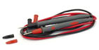
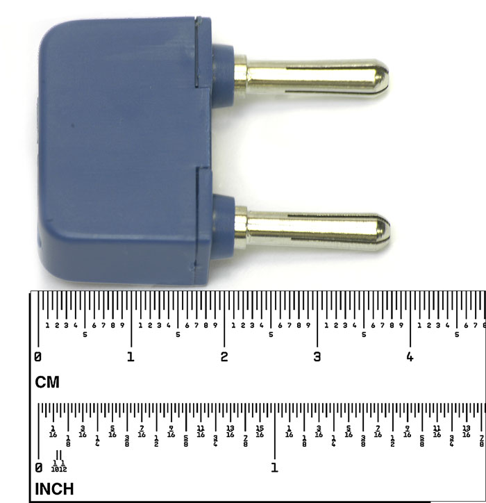
1. Test leads
2. 9V battery
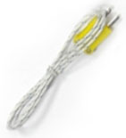
3. Type K temperature probe
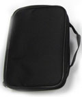
4. Gift box with carrying case
5. USB cable
6. Software

AC Current (Frequency, Duty Cycle) Measurement
- Insert the black test lead banana plug into the "COM" jack.
- For current measurements up to 4000μA AC, set the function switch to the "μA" position and insert the red test lead banana plug into the "μA/mA" jack.
- For current measurements up to 400mA AC, set the function switch to the "mA" position and insert the red test lead banana plug into the "μA/mA" jack.
- For current measurements up to 10A AC, set the function switch to the "10A/Hz/%" position and insert the red test lead banana plug into the "10A" jack.
- Press the "MODE" button to indicate "AC" on the display.
- Remove power from the circuit under test, then open up the circuit at the point where you wish to measure current.
- Touch the black test probe tip to the neutral side of the circuit. Touch the red test probe tip to the "hot" side of the circuit.
- Apply power to the circuit.
- Read the current in the display. In the 10A AC range, right auxiliary display frequency.
- Press and hold the "MODE" button to indicate "Hz".
- Read the frequency in the display.
- Momentarily press the "MODE" button again to indicate "%".
- Read the % duty cycle in the display.
- Press and hold the "MODE" button to return to current measurement.
- Press "EXIT" for 2 seconds into the function of AC+DC. Test DC and AC TRUE Rms.

 CAUTION: Do not make 10A current measurements for longer than 30 seconds. Exceeding 30 seconds may cause damage to the meter and/or the test leads.
AC Voltage (Frequency, Duty Cycle) Measurement
- Insert the black test lead banana plug into the "COM" jack.
- For current measurements up to 4000μA AC, set the function switch to the "μA" position and insert the red test lead banana plug into the "μA/mA" jack.
- For current measurements up to 400mA AC, set the function switch to the "mA" position and insert the red test lead banana plug into the "μA/mA" jack.
- For current measurements up to 10A AC, set the function switch to the "10A/Hz/%" position and insert the red test lead banana plug into the "10A" jack.
- Press the "MODE" button to indicate "AC" on the display.
- Remove power from the circuit under test, then open up the circuit at the point where you wish to measure current.
- Touch the black test probe tip to the neutral side of the circuit. Touch the red test probe tip to the "hot" side of the circuit.
- Apply power to the circuit.
- Read the current in the display. In the 10A AC range, right auxiliary display frequency.
- Press and hold the "MODE" button to indicate "Hz".
- Read the frequency in the display.
- Momentarily press the "MODE" button again to indicate "%".
- Read the % duty cycle in the display.
- Press and hold the "MODE" button to return to current measurement.
- Press "EXIT" for 2 seconds into the function of AC+DC. Test DC and AC TURE Rms.

CAUTION: Do not make 10A current measurements for longer than 30 seconds. Exceeding 30 seconds may cause damage to the meter and/or the test leads.
DC Current Measurement
- Insert the black test lead banana plug into the "COM" jack.
- For current measurements up to 4000μA DC, set the function switch to the "μA" position and insert the red test lead banana plug into the "μA/mA" jack.
- For current measurements up to 400mA DC, set the function switch to the "mA" position and insert the red test lead banana plug into the "μA/mA" jack.
- For current measurements up to 10A DC, set the function switch to the "10A/Hz/%" position and insert the red test lead banana plug into the "10A" jack.
- Press the "MODE" button to indicate "DC" on the display.
- Remove power from the circuit under test, then open up the circuit at the point where you wish to measure current.
- Touch the black test probe tip to the negative side of the circuit. Touch the red test probe tip to the positive side of the circuit.
- Apply power to the circuit.
- Read the current in the display.

CAUTION: Do not make 10A current measurements for longer than 30s. Exceeding 30s may cause damage to the meter and/or the test leads.
DC Voltage Measurement
- Set the function switch to the "VDC" position.
- Insert the black test lead banana plug into the "COM" jack. Insert the red test lead banana plug into the "Ω/
 /
/ /CAP/V/°F/°C/Hz%" jack.
- Touch the black test probe tip to the negative side of the circuit. Touch the red test probe tip to the positive side of the circuit.
- Read the voltage in the display.

CAUTION: Do not measure DC voltages if a motor on the circuit is being switched ON or OFF. Large voltage surges may occur that can damage the meter.
mV Voltage Measurement
- Set the function switch to the "mV" position.
- Press the "MODE" button to indicate "DC" or "AC", or in AC range press "EXIT" for two seconds and chose "AC+DC"
- Insert the black test lead banana plug into the "COM" jack. Insert the red test lead banana plug into the "Ω///CAP/V/°F/°C/Hz%" jack.
- Touch the black test probe tip to the negative side of the circuit. Touch the red test probe tip to the positive side of the circuit.
- Read the mV voltage in the main display.

CAUTION: Do not measure mV voltages if a motor on the circuit is being switched ON or OFF. Large voltage surges may occur that can damage the meter.
Resistance Measurements
- Set the function switch to the "Ω///CAP" position.
- Insert the black test lead banana plug into the "COM" jack. Insert the red test lead banana plug into the "Ω///CAP/V/°F/°C/Hz%" jack.
- Press the "MODE" button to indicate "Ω" on the display.
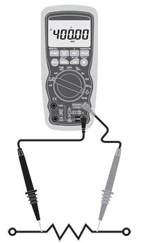
- Touch the test probe tips across the circuit or part under test. It is best to disconnect one side of the part under test so the rest of the circuit will not interfere with the resistance reading.
- Read the resistance in the display.
WARNING: To avoid electric shock, disconnect power to the unit under test and discharge all capacitors before taking any resistance measurements. Remove the batteries and unplug the line cords.
Capacitance Measurements
- Set the function switch to the "Ω///CAP" position.
- Insert the black test lead banana plug into the "COM" jack.
- Insert the red test lead banana plug into the "Ω///CAP/V/°F/°C/Hz%" jack.
- Press the "MODE" button to indicate "F".
- Touch the test leads to the capacitor to be tested.
- Read the capacitance value in the display
WARNING: To avoid electric shock, disconnect power to the unit under test and discharge all capacitors before taking any capacitance measurements. Remove the batteries and unplug the line cords.
Continuity Check
- Set the function switch to the "Ω///CAP" position.
- Insert the black lead banana plug into the "COM" jack. Insert the red test lead banana plug into the "Ω///CAP/V/°F/°C/Hz%" jack.
- Press the "MODE" button to indicate "" and "Ω" on the display
- Touch the test probe tips to the circuit or wire you wish to check.
- If the resistance is less than approximately 35Ω, the audible signal will sound. If the circuit is open, the display will indicate "OL".
WARNING: To avoid electric shock, never measure continuity on circuits or wires that have voltage on them.
Diode Test
- Set the function switch to the "Ω///CAP" position.
- Insert the black test lead banana plug into the "COM" jack. Insert the red test lead banana plug into the "Ω///CAP/V/°F/°C/Hz%" jack.
- Press the "MODE" button to indicate "" and "V" on the display.
- Touch the test probes to the diode under test. Forward voltage will typically indicate 0.400 to 0.700V. Reverse voltage will indicate "OL". Shorted devices will indicate near 0V and an open device will indicate "OL" in both polarities.
Temperature Measurements
- Set the function switch to the "Temp" position.
- Insert the Temperature Probe into the input jacks, making sure to observe the correct polarity.
- Press the "MODE" button to indicate "°C" or "°F"
- Touch the Temperature Probe head to the part whose temperature you wish to measure. Keep the probe touching the part under test until the reading stabilizes (about 30 seconds).
- Read the temperature in the display.
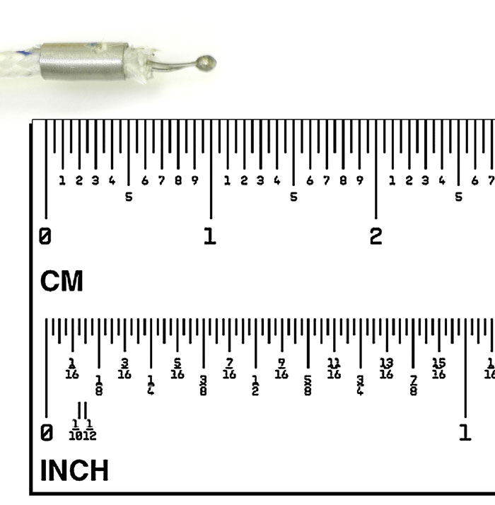
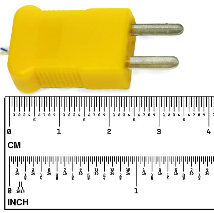
Note: The temperature probe is fitted with a type K mini connector. A mini connector to banana connector adaptor is supplied for connection to the input banana jacks.
Frequency (Duty Cycle) Measurements (Electronic)
- Set the function switch to the "Hz/%" position.
- Insert the black lead banana plug into the "COM" jack.
- Insert the red test lead banana plug into the "Ω///CAP/V/°F/°C/Hz%" jack.
- Touch the test probe tips to the circuit under test.
- Read the frequency on the display.
- Press the "MODE" button to indicate "%".
- Read the % duty cycle in the display.