|
|
ADS-6122H-VGA-DMM-DEC Digital Storage Oscilloscope
ADS-6122H-VGA-DMM-DEC Digital Storage Oscilloscope
|
|
Digital storage oscilloscope. Dual channels + external trigger; Bandwidth: 100MHz; Max. Sample rate: 1GSa/s; Max. Memory Depth: 40Mpts; 12 bit; Waveform math: +, -, ×, /; 28 types Automatic measurement; 8” 800x600 64K color TFT LCD display; USB device, USB host, LAN, Pass/Fail, VGA; Built-in DMM (ADS-6000DMM option installed); Serial bus (RS-232, SPI, I²C) decoding (ADS-6000DEC option installed;) Power Supply 100-240V; Dimensions (WxHxD): 13.4x7x3.5in/340x177x90mm; Weight: 5.7lb/2.6kg.
|
|
ADS-6122H-VGA-DMM-DEC Digital Storage Oscilloscope offers high vertical resolution (12 bit), 2 channels with 100MHz bandwidth, 1GSa/s sample rate, 8″ color TFT-LCD display with 800x600 resolution, large amounts of memory (40Mpts), USB flash storage support, LAN interface. ADS-6122H-VGA-DMM-DEC Digital Storage Oscilloscope is very slim and lightweight.
ADS-6122H-VGA-DMM-DEC digital oscilloscope offers buil-in digital multimeter (with option ADS-6000DMM installed) and serial bus decoding (with option ADS-6000DEC installed).
ADS-6122H-VGA-DMM-DEC comes with VGA output (with option ADS-6000VGA installed) that is very helpful to a teacher who wants to demonstrate oscilloscopes functions on the large screen. ADS-6122H-VGA-DMM-DEC digital oscilloscope could be connected to a large screen TV, a projector or any other screen and used for training and demonstrations. Perfect oscilloscope for education!
Specifications
|
Bandwidth
|
100MHz
|
|
Sample Rate
|
1GS/s
|
|
Vertical Resolution (A/D)
|
12 bits
|
|
Record length
|
40M
|
|
Waveform Refresh Rate
|
75,000 wfms/s
|
|
Horizontal Scale (s/div)
|
2ns/div - 1000s/div, step by 1 - 2 - 5
|
|
Rise Time (at input, typical)
|
≤3.5ns
|
|
Channel
|
2 + 1 (external)
|
|
Display
|
8" color LCD, 800 x 600 pixels
|
|
Input Impedance
|
1MΩ ± 2%, in parallel with 15pF ± 5pF; 50Ω ± 2%
|
|
Channel Isolation
|
50Hz : 100 : 1, 10MHz : 40 : 1
|
|
Max Input Voltage
|
1MΩ ≤ 300Vrms; 50Ω ≤ 5Vrms
|
|
DC Gain Accuracy
|
±3%
|
|
DC Accuracy
|
average≥16 : ±(3% reading + 0.05 div) for ΔV
|
|
Probe Attenuation Factor
|
0.001X - 1000X, step by 1 - 2 - 5
|
|
LF Respond (AC, -3dB)
|
≥5Hz (at input, AC coupling, -3dB)
|
|
Sample Rate / Relay Time Accuracy
|
±1ppm
|
|
Interpolation
|
sin(x) / x
|
|
Interval (ΔT) Accuracy (full bandwidth)
|
Single: ±(1 interval time + 1ppm x reading + 0.6ns);
Average > 16: ±(1 interval time + 1ppm x reading + 0.4ns)
|
|
Input Coupling
|
DC, AC, and GND
|
|
Vertical Sensitivity
|
1mV/div - 10V/div (at input)
|
|
Trigger Type
|
Edge, Video, Pulse, Slope, Runt, Windows, Timeout, Nth Edge, Logic, I²C, SPI, RS-232
|
|
Bus Decoding
|
I²C, SPI, RS-232
|
|
Trigger Mode
|
Auto, Normal, and Single
|
|
Trigger Level
|
±2000div (1mv/div), ±1000div (2mv/div), ±400div (5mv/div), ±200div (10mv/div), ±100div (20mv/div), ±40div (50mv/div), ±200div (100mv/div), ±100div (200mv/div), ±40div (500mv/div), ±20div (1v/div), ±100div (2v/div), ±40div (5v/div), ±20div (10v/div)
|
|
Line / Field Frequency (video)
|
NTSC, PAL and SECAM standard
|
|
Cursor Measurement
|
ΔV, and ΔT between cursors, ΔV and ΔT between cursors, auto-cursor
|
|
Automatic Measurement
|
Vpp, Vavg, Vrms, Freq, Period, Week RMS, Cursor RMS, Vmax, Vmin, Vtop, Vbase, Vamp, Overshoot, Phase, Preshoot, Rise Time, Fall Time, +Width, -Width, +Duty, -Duty, Duty Cycle, Delay A→B ↑, Delay A→B↓, +Pulse Count, -Pulse Count, Rise Edge Count, Fall Edge Count
|
|
Waveform Math
|
+, -, ×, /, FFT
|
|
Waveform Storage
|
100 waveforms
|
Lissajou's
Figure
|
Bandwidth
|
full bandwidth
|
|
Phase Difference
|
±3 degrees
|
|
Communication Interface
|
USB host, USB device, USB port for PictBridge, Trig Out (P/F), LAN, VGA
|
|
Frequency Counter
|
available
|
|
Power Supply
|
100V - 240V AC, 50/60Hz, CAT II
|
|
Power Consumption
|
<15W
|
|
Fuse
|
2A, T class, 250V
|
|
Battery (optional)
|
3.7V, 13200mA
|
|
Dimension (W x H x D)
|
13.4x7x3.5 in / 340 x 177 x 90 mm
|
|
Weight
|
5.7 lb / 2.60 kg
|
Multimeter Specifications
|
Full Scale Reading
|
3¾ digits (max 4000 count)
|
Diode
|
0V -1.5V
|
|
Input Impedance
|
10MΩ
|
Continuity Test
|
<50 (±30) beeping
|
|
Capacitance
|
51.2nF - 100uF: ±(3% ± 3 digits)
|
|
Voltage
|
VDC: 400mV, 4V, 400V: ±(1 ± 1 digit); max input: DC 1000V
VAC: 4V, 40V, 400V: ±(1 ± 3 digits); frequency: 40Hz - 400Hz; max input: AC 750V (virtual value)
|
|
Current
|
DC: 40mA, 400mA: ±(1.5% ± 1 digit); 10A: ±(3% ± 3 digits)
AC: 40mA: ±(1.5% ± 3 digits), 400mA: ±(2% ± 1 digit), 10A: ±(3% ± 3 digits)
|
|
Impedance
|
400Ω: ±(1% ± 3 digits), 4KΩ - 40MΩ: ±(1% ± 1 digit)
|
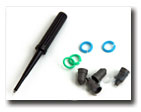
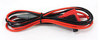
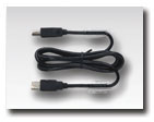
Accessories
Standard
- Probes x2
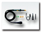 
- Test leads
- USB cable
- Power cord
User's Manual is not included.
You can see it on your oscilloscope's screen by pressing HELP
| ADS-6122H-VGA-DMM-DEC Digital Storage Oscilloscope - front view |
|
|
| ADS-6122H-VGA-DMM-DEC Digital Storage Oscilloscope - rear view |
|
|
| ADS-6122H-VGA-DMM-DEC Digital Storage Oscilloscope - left view |
|
|
|
| ADS-6122H-VGA-DMM-DEC Digital Storage Oscilloscope - right view |
|
|
| ADS-6122H-VGA-DMM-DEC Digital Storage Oscilloscope - accessories |
|
|
| ADS-6122H-VGA-DMM-DEC Digital Storage Oscilloscope - optional battery installation |
|
|
|
| ADS-6122H-VGA-DMM-DEC Digital Storage Oscilloscope |
|
|
Frequently Asked Questions
After the oscilloscope is powered on the display remains dark, what should I do?
The signal is displayed as ladder like waveform
There is wave form displayed, but it is not stable
When changing the horizontal sweep on the digital oscilloscope at different horizontal points observed inexplicable change in the form of the same signal, why is this happening?
| After the oscilloscope is powered on the display remains dark, what should I do? |
|
Please implement the following fault treatment procedure.
- Check whether the power cable is connected properly.
- Ensure the power switch is turned on.
- Restart the instrument after completing the checks above.
- If the oscilloscope still can not work normally, please call for service.
Up
|
| The signal is displayed as ladder like waveform |
- The time base setting maybe is too slow. Turn the horizontal SCALE knob to increase horizontal resolution.
- Maybe the display Type is set to "Vectors". Set it to "Dots" mode.
Up
|
| There is wave form displayed, but it is not stable |
- Check whether the Source item in the TRIG MODE menu is in conformity with the signal channel used in the practical application.
- Check on the trigger Type item: The common signal chooses the Edge trigger mode for Type and the video signal the Video. Only if a proper trigger mode is applied, the wave form can be displayed steadily.
- Try to change the trigger coupling into the high frequency suppress and the low frequency suppress to smooth the high frequency or low frequency noise triggered by the interference.
Up
|
| When changing the horizontal sweep on the digital oscilloscope at different horizontal points observed inexplicable change in the form of the same signal, why is this happening? |
|
In fact, this is not a problem.
Just keep in mind that you're using a digital oscilloscope, which digitizes the signal with different sampling rates depending on the selected horizontal sweep, and then connects the digitized points with strait line while restoring the real shape of the signal.
Your first screen shows that you are measuring voltage 50 Hz with the 10 ms / div sweep and a sampling frequency of 20 kHz Ks/s
One signal period (20 ms), digitized in this mode, 20E-03 (sec) * 20E03 (1/sec) = 400 points. This is enough to properly restore and interpolate a sine wave of 50 Hz (i.e. in a period of 20 ms).
Normal display, with a sweep 10 ms / div:
Distortion of the same signal at 10 s / div sweep
Your second screen is set to sweep 10 sec / div, and sample rate on a sweep turned to 20 samples per second (20 Sa / s). I.e. one signal period 20 ms had: 20E-03 (sec) * 20 (1/sec) = 0.4 points. That means that to restore (to interpolate the points) a sine wave with less than one point in time is impossible, so you get this mess (known as "aliasing" or a false frequency) formed by the beats of the measured frequency and sampling frequency.
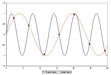
In order to correctly install a data collection in a digital oscilloscope one should follow a simple rule - the sampling rate must be at least 5-10 times higher than the frequency signal, in that case you will not have the issues that we just discussed.
This applies to all digital oscilloscopes and in no way connected to any particular make or model of oscilloscope or its probes.
Up
|
Back to the section
|
|


