|
||||
|
|
|||
|
||||
|
|
|||
|
Search
Log in
|
ATH-8240 Programmable Electronic Load
Programmable electronic load is designed for the operation as a load when testing, setting and adjusting power blocks, amplifiers, sound reproducers and other radio equipment with supply voltage of up to 150V, load current of up to 240A and accepted power of up to 2400 W. Main Features:
Specifications:
Power-on-self-testVerify that you have received the following items from your supplier. If anything is missing, contact us.
At first, please make sure the electronic load has been correctly connected and powered on. Please refer to the following for the detailed operation steps.
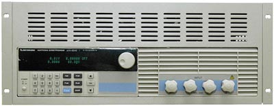
Electronic Load Operation InstructionsFront Panel OperationPlease refer to the picture 3-2 for the front panel of electronic load.
The upper half is black VFD display screen and knob. The bottom half, left side to right side, is Numeric keys 0-9, ESC key, Function keys, Up-Down keys, Enter key, Input terminal and Output terminal.
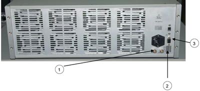
1) 0-full range current, in correspond to 0-10V output, Oscilloscope can be connected by here to observe dynamic waveforms. 2) Remote Measurement terminals and trigger input/output interface. 3) Multifunctional communication interface GPIB, RS-232, RS-425, USB. Keypad Directions
Menu OperationPress the key Shift+Menu to access to the menu function and theVFD display screen shows the menu items. Select the menu items by pressing the ▲ and ▼ keys or by rotating the knob, and then press the key Enter to enter in the menu item you wanted. Or you can press the key Esc to return to the last menu.
Basic Operation ModeThere are four operation modes for electronic load:
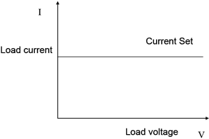
Constant Current Operation Mode (CC)In this mode, the electronic load will sink a current in accordance with the programmed value regardless of the input voltage. Please refer to the picture 4-1. If maximum current value of the measured power supplier is lessen than the constant current value set, the electronic load might fail to adjust itself to the constant current and the voltage of the measured power supplier could be changed to be low.
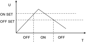
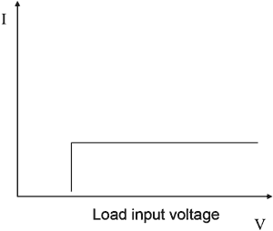
Setting up a Standard Constant Current ModePress the key I-SET, then the VFD display will show STANDARD CURR=xxxxxxxxA, the current constant current value. Press the numeric keys and decimal point key to enter the constant current value required, followed by pressing the key Enter to confirm. Then the load will enter into the standard constant current. If the input state is in OFF state, then the right upper corner of the VFD display will show the word OFF. Press the key On/Off to change the input state into ON state. Then the right upper corner of the VFD display will show the word CC or Unreg. Showing CC means the load has been successfully set into the expected constant current value; showing Unreg means the load couldn't adjust itself to the expected constant current value. Please check if the measured power supplier has been correctly connected and turned on; make sure if the expected constant current value is in the range of the measured power supplier. If you want to fine tune the constant current value, you can rotate the selective encoder knob to adjust the value. Rotating clockwise is to increase the value while rotating anti-clockwise is to decrease the value. Note: if the constant current value you want to set is beyond the maximum constant current value of the load, the current value will stop to be increased even if you still rotate theselective encoder knob clockwise. Then the right lower corner of the VFD display shows the constant current value you set, among which, a cursor shows under one number, meaning this number requires fine tuning. If users want to change the fine tuning accuracy, just press the rotary encoder knob in which a key is included. Every time when you press the rotary encoder once, the cursor will move forward to the previous number. Loading and Unloading Constant Current ModeLoading and unloading mode can well protect the measured power supplier from damage. When the voltage of the measured power supplier begins to increase, the load will automatically adjust itself to the open-circuit state, and begin to carry the measured power supplier and adjust itself to the current value set only when the voltage of the measured power supplier has been increased to the ONSET loading voltage. When the voltage of the measured power supplier begins to decrease and has been decreased to the OFFSET unloading value, the load will automatically adjust itself to the open-circuit state. If the ONSET loading voltage value is higher than the OFFSET unloading voltage value, the load can be avoided from frequent carrying and unloading at the critical point of unloading voltage; thus the measured power supplier can be well protected.
When in standard constant current mode, press the key Shift+1 (V_Level) and enter into the loading and unloading constant current mode. When the VFD display shows ONSET VOLT=xxxxxxxxV indicating the current loading voltage, press the numeric keys and decimal point key to enter the loading voltage value required, followed by pressing the key Enter to confirm. Then the VFD will shows OFFSET VOLT=xxxxxxxxV indicating the current unloading voltage. Press the numeric keys and decimal point key to enter the unloading voltage value required, followed by pressing the key Enter to confirm. In this way, the load will enter into the loading and unloading constant current mode. If the input state is in OFF state, then the right upper corner of the VFD display will show the word OFF. Press the key On/Off to change the input state into ON state. Then the right upper corner of the VFD display will show the word CC_UN or Unreg. Showing CC_UN means the load has successfully set into the expected constant current value; showing Unreg means the load could not adjust itself to the expected constant current value. Please check if the measured power supplier has been correctly connected and turned on; make sure if the voltage is normal and if the expected constant current value is in the range of the measured power supplier. In loading and unloading constant current mode, press the key Shift+1 (V_Level), the load will back into the standard constant current mode. Soft Start Constant Current ModeSoft start constant current mode functions as an inductive load, simulating inductance value which is in direct proportion with the rise time of soft start. In this mode, the measured power supplier can be avoided from current strike damage.
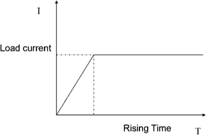
When in standard constant current mode, press the key Shift+2 (S_Start) to enter into the soft start constant current mode. When the VFD display shows Rising TM=xxxxxxxxvmS indicating the current rising time, press the numeric keys and decimal point key to enter the rising time required, followed by pressing the key Enter, In this way, the load will enter into the soft start constant current mode. If the input state is in OFF state, then the right upper corner of the VFD display will show the word OFF. Press the key On/Off to change the input state into ON state. Then the right upper corner of the VFD display will show the word CC_S or Unreg. Showing CC_S means the load has been successfully set into the expected constant current value; showing Unreg means the load couldn't adjust itself to the expected constant current value. Please check if the measured power supplier has been correctly connected and turned on; make sure if the expected constant current value is in the range of the measured power supplier. In loading and unloading constant current mode, press the key Shift+2 (S_Start), the load will back into the standard constant current mode. Note: The rise time set is automatically regulated to be the round number times of 20uS. Constant Current Shifting into Constant Voltage ModeIn constant current shifting into constant voltage mode, the measured power supplier can be avoided from current strike damage.
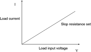
When in standard constant current mode, press the key Shift+4 (CC+CV) to enter into the constant current shifting into constant voltage mode. When the VFD display shows CC TO CV VOLT=xxxxxxxxV indicating the current constant voltage value, press the numeric keys and decimal point key to enter the constant voltage value required followed by pressing the key Enter to confirm. In this way, the load will enter into the constant current shifting into constant voltage mode. If the input state is in OFF state, then the right upper corner of the VFD display will show the word OFF. Press the key On/Off to change the input state into ON state. Then the right upper corner of the VFD display will show the word CC+CV or Unreg. Showing CC+CV means the load has been successfully set into the expected constant current value; showing Unreg means the load could not adjust itself to the expected constant current value. Please check if the measured power supplier has been correctly connected and turned on; make sure if the voltage is normal. In loading and unloading constant current mode, press the key Shift+4 (CC+CV), the load will back into the standard constant current mode. Constant Resistant Operation Mode (CR)In this mode, the module will sink a current linearly proportional to the input voltage in accordance with the programmed resistance. Please refer to the picture 4-5. Note: when the voltage of the measured power supplier is too high and the resistance set is too low, it will result in the consumed current higher than the maxim output current of the measured power supplier, or result in the loads failing to adjust itself automatically to the constant resistance, even result in the load shock.
Setting up a Standard Constant Resistance ModePress the key R-SET, then the VFD display will show STANDARD RESI=xxxxxxxxΩ indicating the current constant resistance. Then Press the numeric keys and decimal point key to enter the constant resistance value required, followed by pressing the key Enter. In this way, the load will enter into the standard constant resistance mode. If the input state is in OFF state, then the right upper corner of the VFD display will show the word OFF. Press the key On/Off to change the input state into ON state. Then the right upper corner of the VFD display will show the word CR or Unreg. Showing CR means the load has been successfully set into the expected constant resistance value; showing Unreg means the load couldnot adjust itself to the expected constant resistance value. Please check if the measured power supplier has been correctly connected and turned on; make sure if the output current of the measured power supplier is in the range of the current value that the expected resistance can absorb. If you want to fine tune the constant resistance value, you can rotate the selective encoder knob to adjust the value. Rotating clockwise is to increase the value while rotating anti-clockwise is to decrease the value. Then the right lower corner of the VFD display shows the constant resistance value you set, among which, a cursor shows under one number, meaning this number requires fine tuning. If users want to change the fine tuning accuracy, just press the rotary encoder knob in which a key is included. Every time when you press the rotary encoder once, the cursor will move forward to the previous number. Loading and Unloading Constant Resistance ModeAs for the loading and unloading mode theory, please refer to the illustration 4-2. When in standard constant resistance mode, press the key Shift+1 (V_Level) to enter into the constant loading and unloading constant resistance mode. When the VFD display shows ONSET VOLT=xxxxxxxxV indicating the current loading voltage, press the numeric keys and decimal point key to enter the loading voltage value required followed by pressing the key Enter to confirm. Then the VFD will shows OFFSET VOLT=xxxxxxxxV indicating the current unloading voltage. Press the numeric keys and decimal point key to enter the unloading voltage value required, followed by pressing the key Enter to confirm. In this way, the load will enter into the loading and unloading constant resistance mode. If the input state is in OFF state, then the right upper corner of the VFD display will show the word OFF. Press the key On/Off to change the input state into ON state. Then the right upper corner of the VFD display will show the word CR_UN or Unreg. Showing CR_UN means the load has been successfully set into the expected constant resistance value; showing Unreg means the load could not adjust itself to the expected constant resistance value. Please check if the measured power supplier has been correctly connected and turned on; make sure if the voltage is normal and if the output current of the measured power supplier is in the range of the current value that the expected resistance can absorb. In loading and unloading constant current mode, press the key Shift+1 (V_Level), the load will back into the standard constant resistance mode. Constant Resistance Shifting into Constant Voltage Mode
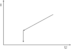
In constant resistance shifting into constant voltage mode, the measured power supplier can be avoided from current strike damage. When in standard constant current mode, press the key Shift+5 (CR+CV) to enter into the constant current shifting into constant voltage mode. When the VFD display shows CR TO CV VOLT=xxxxxxxxV indicating the current constant voltage value, press the numeric keys and decimal point key to enter the constant voltage value required followed by pressing the key Enter to confirm. In this way, the load will enter into the constant resistance shifting into constant voltage mode. If the input state is in OFF state, then the right upper corner of the VFD display will show the word OFF. Press the key On/Off to change the input state into ON state. Then the right upper corner of the VFD display will show the word CR+CV or Unreg. Showing CR+CV means the load has been successfully set into the expected constant resistance value; showing Unreg means the load could not adjust itself to the expected constant resistance value. Please check if the measured power supplier has been correctly connected and turned on; make sure if the voltage is normal. In loading and unloading constant resistance mode, press the key Shift+5 (CR+CV), the load will back into the standard constant resistance mode. Constant Voltage Operation Mode (CV)In this mode, the electronic load will attempt to sink enough current to control the source voltage to the programmed value. Please refer to the picture 4.7. Note: When the voltage of the measured power supplier is lessen than the voltage value set or the maximum input current is beyond the maxim current that the load can absorb, the load couldn't control the voltage to the value set.
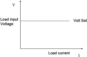
Setting up a Standard Constant Voltage ModePress the key V-SET, then the VFD display will show STANDARD VOLT=xxxxxxxxV indicating the current constant voltage value. Then Press the numeric keys and decimal point key to enter the constant voltage value required, followed by pressing the key Enter. In this way, the load will enter into the standard constant voltage mode. If the input state is in OFF state, then the right upper corner of the VFD display will show the word OFF. Press the key On/Off to change the input state into ON state. Then the right upper corner of the VFD display will show the word CV or Unreg. Showing CV means the load has been successfully set into the expected constant voltage value; showing Unreg means the load couldn't adjust itself to the expected constant voltage value. Please check if the measured power supplier has been correctly connected and turned on; make sure if the voltage of the measured power supplier is normal and if the output current is beyond the maximum current that the load can carry. If you want to fine tune the constant voltage value, you can rotate the selective encoder knob locating at the right upper corner of the front panel to adjust the value. Rotating clockwise is to increase the value while rotating anti-clockwise is to decrease the value. Note: if the constant voltage value you want to set is beyond the maximum constant voltage value of the load, the current value will stop to be increased even if you still rotate theselective encoder knob clockwise. Then the right lower corner of the VFD display shows the constant voltage value you set, among which, a cursor shows under one number, meaning this number requires fine tuning. If users want to change the fine tuning accuracy, just press the rotary encoder knob in which a key is included. Every time when you press the rotary encoder once, the cursor will move forward to the previous number. Loading and Unloading Constant Voltage ModeAs for the loading and unloading mode theory, please refer to the 4-2 illustration. When in standard constant voltage mode, press the key Shift+1 (V_Level) to enter into the constant loading and unloading constant voltage mode. When the VFD display shows ONSET VOLT=xxxxxxxxV indicating the current loading voltage, press the numeric keys and decimal point key to enter the loading voltage value required followed by pressing the key Enter to confirm. Then the VFD will shows OFFSET VOLT=xxxxxxxxV indicating the current unloading voltage. Press the numeric keys and decimal point key to enter the unloading voltage value required, followed by pressing the key Enter to confirm. In this way, the load will enter into the loading and unloading constant voltage mode. If the input state is in OFF state, then the right upper corner of the VFD display will show the word OFF. Press the key On/Off to change the input state into ON state. Then the right upper corner of the VFD display will show the word CV_UN or Unreg. Showing CV_UN means the load has been successfully set into the expected constant voltage value; showing Unreg means the load couldn't adjust itself to the expected constant voltage value. Please check if the measured power supplier has been correctly connected and turned on; make sure if the voltage is normal and if the maximum output current of the measured power supplier is in the range of the maximum current that the load can absorb. In loading and unloading constant voltage mode, press the key Shift+1 (V_Level), the load will back into the standard constant voltage mode. Soft Start Constant Voltage ModeSoft start constant voltage mode functions as a condensive load, simulating electric capacity which is in direct proportion with the rise time of soft start. In this mode, the measured power supplier can be avoided from current strike damage.
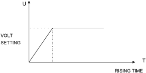
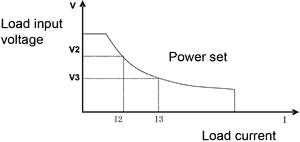
When in standard constant voltage mode, press the key Shift+2 (S_Start) to enter into the soft start constant voltage mode. When the VFD display shows RISING TM=xxxxxxxxvmS indicating the current rising time, press the numeric keys and decimal point key to enter the rising time required, followed by pressing the key Enter, In this way, the load will enter into the soft start constant voltage mode. If the input state is in OFF state, then the right upper corner of the VFD display will show the word OFF. Press the key On/Off to change the input state into ON state. Then the right upper corner of the VFD display will show the word CV_S or Unreg. Showing CV_S means the load has been successfully set into the expected constant voltage value; showing Unreg means the load couldn't adjust itself to the expected constant voltage value. Please check if the measured power supplier has been correctly connected and turned on; make sure if the maximum output current of the measured power supplier is in the range of the maximum current that the load can absorb. In loading and unloading constant voltage mode, press the key Shift+2 (S_Start), the load will back into the standard constant voltage mode. Note: The rise time which is set is automatically regulated to be the round number times of 20µS. Constant Power Operation Mode (CW)In this mode, the electronic loads will consume a constant power. Please refer to the picture 4-9. If the load input voltage value increase, the load input current will decrease. Therefore the load power (=V * I) will remain in the power set.
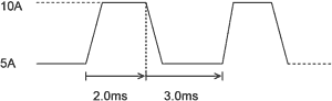
Setting up a Standard Constant Power ModePress the key P-SET, then the VFD display will show STANDARD POWER=xxxxxxxxW indicating the current constant power. Then Press the numeric keys and decimal point key to enter the constant power value required, followed by pressing the key Enter. In this way, the load will enter into the standard constant power mode. If the input state is in OFF state, then the right upper corner of the VFD display will show the word OFF. Press the key On/Off to change the input state into ON state. Then the right upper corner of the VFD display will show the word CW or Unreg. Showing CW means the load has been successfully set into the expected constant power value; showing Unreg means the load couldn't adjust itself to the expected constant power value. Please check if the measured power supplier has been correctly connected and turned on; make sure if the voltage of the power supplier is normal and the maximum output current of the measured power supplier is undercurrent. If you want to fine tune the constant power value, you can rotate the selective encoder knob to adjust the value. Rotating clockwise is to increase the value while rotating anti-clockwise is to decrease the value. Then the right lower corner of the VFD display shows the constant power value you set, among which, a cursor shows under one number, meaning this number requires fine tuning. If users want to change the fine tuning accuracy, just press the rotary encoder knob in which a key is included. Every time when you press the rotary encoder once, the cursor will move forward to the previous number. Loading and Unloading Constant Power ModeAs for the loading and unloading mode theory, please refer to the 4-2 illustration. When in standard constant power mode, press the key Shift+1 (V_Level) to enter into the constant loading and unloading constant power mode. When the VFD display shows ONSET VOLT=xxxxxxxxV indicating the current loading voltage, press the numeric keys and decimal point key to enter the loading voltage value required followed by pressing the key Enter to confirm. Then the VFD will shows OFFSET VOLT=xxxxxxxxV indicating the current unloading voltage. Press the numeric keys and decimal point key to enter the unloading voltage value required, followed by pressing the key Enter to confirm. In this way, the load will enter into the loading and unloading constant power mode. If the input state is in OFF state, then the right upper corner of the VFD display will show the word OFF. Press the key On/Off to change the input state into ON state. Then the right upper corner of the VFD display will show the word CW_UN or Unreg. Showing CW_UN means the load has been successfully set into the expected constant power value; showing Unreg means the load couldn't adjust itself to the expected constant power value. Please check if the measured power supplier has been correctly connected and turned on; make sure if the voltage is normal and if the output current of the measured power supplier is in the range of the current that the expected power can absorb. In loading and unloading constant power mode, press the key Shift+1 (V_Level), the load will back into the standard constant power mode. Dynamic Testing OperationDynamic testing operation enables the electronic load to periodically switch between two load levels. This function can be used to test the transient characteristics of the measured power supplier. Dynamic testing operation can be turned on and off by pressing the key Shift+Tran at the front panel. Before you turn on dynamic testing operation, you should set all of the parameters associated with dynamic testing operation by pressing the key Shift+S-Tran, including: Value A, A pulse time, Rising time from value A to value B, Value B, B pulse time, Falling time from value B to value A and dynamic testing operation mode. There are three kinds of dynamic testing operation mode: continuous mode, pulse mode and trigger mode. Continuous Mode (CONTINUOUS)In this mode, the electronic load will periodically switch between value A and value B when the dynamic testing operation is turned on.
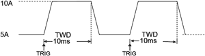
Pulse Mode (PULSE)In this mode, when the dynamic testing operation is turned on, the electronic load will switch to value B as receiving one trigger signal, taking the pulse time (TWD) of value B, Load will return to Value A.
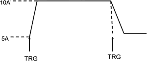
Trigger Mode (TRIGGER)In this mode, when the dynamic testing operation is turned on, the electronic load will switch the state between value A and value B once receiving a triggering signal.
Setting up Dynamic testing operation ParametersPress the key Shift+6 (S_Tran), then the load VFD display shows LEVEL A CURR=xxxxxxxxA indicating the current value A set. Press the numeric keys and decimal point key to enter the current value required, followed by pressing the key Enter to confirm. Then the load VFD display shows WIDTH A TM=xxxxxxxxmSindicating the current lasting time of current value A set. Press the numeric keys and decimal point key to enter the lasting time required, followed by pressing the key Enter to confirm. Then the load VFD display shows RISING TM=xxxxxxxxmSindicating the current rising time set from value A to value B. Press the numeric keys and decimal point key to enter the rising time required, followed by pressing the key Enter to confirm. Then the load VFD display shows LEVEL B CURR=xxxxxxxxA indicating the current value B set. Press the numeric keys and decimal point key to enter the current value required, followed by pressing the key Enter to confirm. Then the load VFD display shows WIDTH B TM=xxxxxxxxmSindicating the current lasting time of current value B set. Press the numeric keys and decimal point key to enter the lasting time required, followed by pressing the key Enter to confirm. Then the load VFD display shows FALLING TM=xxxxxxxxmSindicating the current falling time set from value B to value A. Press the numeric keys and decimal point key to enter the falling time required, followed by pressing the key Enter to confirm. Then the load VFD display shows TRANMODE CONTINUOUS / TRANMODE PULSE / TRNMODE TRIGGER indicating the current dynamic testing operation mode. Press the key ▲ or ▼ to choose the dynamic testing operation mode you want, followed by pressing the key Enter to confirm. Waveform ControlSquare WaveWhen the rise time and falling time are both set as zero and the dynamic testing operation mode is set as continuous mode, the output wave is square wave. The output frequency is the inverse of the lasting time sum of current A and current B. Since the minimum accuracy of all the time is set as 20uS, the load can read the square wave with the maximum frequency of 25KHz and duty cycle of 50%. Triangular WaveWhen the lasting time of both current A and current B are set as zero and the dynamic testing operation mode is continuous mode, the output wave is triangular wave. The output frequency is the inverse of the sum of the rising time and falling time. Since the minimum accuracy of all the time is set as 20uS, the load can read the triangular wave with the maximum frequency of 25KHz. Since the rising edge and falling edge of the triangular wave are all step wave with 20uS output frequency, the ideal degree of triangular wave is in inverse proportion to the its output frequency. In extreme situations, the triangular wave might function as square wave; there are 0-100 accuracy difference according to the different rising time and falling time set. Trapezoidal WaveWhen the four time parameters that need to set are all bigger than zero and the dynamic testing operation mode is continuous mode, the load output wave is trapezoidal wave. It has the same frequency characteristics with the triangular wave. Trigger ControlWhen dynamic testing operation mode is set as pulse mode or trigger mode, the trigger control is initiated. There are three trigger modes:
List FunctionThe electronic load is available of list operation function. 8 sets of data can be edited at most and 200 steps can be edited in each set of data. Users can edit the duration of each step, the minimum time of each set of data. Please note that the minimum time should be the round numbers of 0.02mS and ranges from 0.02mS to 1310.7mS. The duration of each step has something to do with the minimum time you set. If the minimum time is set as 0.02mS, then the duration of each step ranges from 0.02mS to1310.7mS; if the minimum time is set as 2mS, then the duration of each step ranges from 2mS to 131070mS. List Operation1) Press the key Shift+0 to enter into the menu operation, and then press the ▲ and ▼ keys to get the item MENU LIST, followed by pressing the Enter key to confirm. Then press the ▲ and ▼ keys to get the item EDIT LIST, followed by pressing the Enter key to confirm. Then press the ▲ and ▼ keys to select the sequential code that need to be set, followed by pressing the Enter key to confirm. 2) When the VFD display shows MINIMUM TM= xxxxxx mS indicating the minimum time that requires to be set. Since this value affects the fine tuning and operable length of all kinds of waveforms, please carefully select the suitable parameters. Then press the key Enter to confirm. The electronic load will go into the following three output modes: LIST CONTINOUS, LIST END HOLD, and LIST END RESET. Press the ▲ and ▼ keys to select one output mode you wanted, followed by pressing the key Enter to confirm. LIST CONTINOUS means continuous output mode. LIST END HOLD means the electronic load will remain the last value you set in the last step when all the steps you set in one set of data have been successfully executed. LIST END RESET means the electronic load will reset to be load off mode when all the steps you set in one set of data have been successfully executed. 3) After pressing the key Enter to confirm, the VFD display will show STEP LENG= xxx, indicating the step length that requires to be set. Then press the numeric keys to input the step length you want to set, followed by pressing the key Enter to confirm. Please note that the step length should be the round number of 1~200. 4) When the VFD display shows STEP 1 CURR=xxxxxA, indicating the current that requires to be set in the first step, press the numeric keys to input the current you want to set in the first step, followed by pressing the key Enter to confirm. When the VFD display shows STEP 1 TM=xxxxx mS, indicating the current duration in the first step, press the numeric keys to input the current duration you want to set in the first step, followed by pressing the key Enter to confirm. 5) If all the steps set have been edited, the VFD display will show EDIT LIST, meaning exit back to the list function. If all the steps set have not been edited, the VFD display will show STEP n CURR=xxxxxA, indicating that data of the N step is being edited. Please finish it according to the operation instruction in last step, step 4). 6) Since list function shares the same storage space with automatic testing function; please make sure that the sequential code that you selected in the list function is the same with that in automatic testing function. If the sequential code which was defined as automatic testing function before, now is defined as list function, the automatic testing function of this sequential code will be deleted and cannot be restored. Executing List FunctionPress the key Shift+0 to enter into menu configuration, and then press the ▲ and ▼ keys to get the item MENU LIS, followed by pressing the key Enter to confirm. Then press the ▲ and ▼ keys to get the item LOAD LIST, followed by pressing the Enter key to confirm. Then press the ▲ and ▼ keys to select the sequential code defined as list function you want to execute, followed by pressing the Enter key to confirm. Since the list function shares the same storage space with automatic testing function, those sequential code defined as the automatic testing function will be automatically shielded when choosing the sequential codes which are defined as list function. Automatic Testing FunctionThe electronic load is available of automatic testing function. 8 sets of data can be edited at most and 50 steps can be edited in each set of data. Each step can be edited as the following six working mode: load off mode, constant current mode, constant voltage mode, constant power mode, constant resistance mode, short circuit mode, and can be edited as the following four types: current comparison, voltage comparison, power comparison and resistance comparison. Besides, the delay time of each step can also be edited. The delay time of each step ranges from 0.1~25.5S, considering the quickness and accuracy. When automatic test is over, the electronic load will indicate if it passes the test or failed. If it fails, the electronic load will sound alarm. Meanwhile, the electronic load can be triggered by front-panel and TRIGGE IN hardware voltage level in the back-panel, and can output the trigger voltage level from the TRIGER OUT terminals on back panel. You can setup it as the voltage level trigger mode or pulse trigger mode, and can have 4 selections of Pass trigger, failure trigger, finish trigger and disabled trigger. Automatic Test Operation1) Press the key Shift+0 to enter into the menu configuration, and then press the ▲ and ▼ keys to get the item MENU AUTO TEST, followed by pressing the Enter key to confirm. Then press the ▲ and ▼ keys to get the item EDIT AUTO TEST, followed by pressing the Enter key to confirm. Then press the ▲ and ▼ keys to select the sequential code that need to be set, followed by pressing the Enter key to confirm. 2) When the VFD display shows STEP LENG= XX, indicating the step length that requires to be set. Then press the numeric keys to input the step length you want to set, followed by pressing the key Enter to confirm. Please note that the step length should be the round numbers of 1~50. 3) When the VFD display shows STEP 1 xxxxx MODE, indicating the working mode selected in the step 1, press the ▲ and ▼ keys to select one mode from he following six working modes, followed by pressing the key Enter to confirm.
4) When the VFD display shows STEP 1 TEST xxxx, indicating the test types. There are four test types: test current, test voltage, test power, test resistance. Press the ▲ and ▼ keys to select one from those four types, followed by pressing the key Enter to confirm. If in last step, step 3), you choose load off mode or short circuit mode, then the electronic load will skip step 4). 5) When the VFD display shows DELAY TM=xx.xS, indicating the delay time of each step. The valid range of the delay time is 0.1~25.5S. The lower value you set, the shorter time the test needs. But in certain circumstances, too lower value may affect the test results because the test has been finished before the power supply reaches static state, so please carefully select the delay time you wanted to set. The recommended delay time is 0.5S. Note: 25.5S is set as suspended mode. So the delay time of a certain step is set as 25.5S, the load will stop to be proceeded to the next step until a trigger is input. The trigger can be made either by the hardware in the back-panel, or by pressing the key Shift+Trigger or the On/Off key in the front panel. 6) When the VFD display shows INPUT xxxx=xxxxxx, indicating the corresponding current value set/voltage value set/ power value set/ resistance value set in working mode. Press the numeric keys to enter the value, followed by pressing the key Enter to confirm. If in step 3), you choose load off mode or short circuit mode, then the electronic load will skip step 6). 7) When the VFD display shows MINIMUM xxxx=xxxxxx, indicating the lower limit of valid comparison, press numeric keys to input the value, followed by pressing the key Enter to confirm. When the VFD display shows MAXIMUM xxxx=xxxxxx, indicating the upper limit of valid comparison, press numeric keys to input the value, followed by pressing the key Enter to confirm. If all the steps set have been edited, the VFD display will show EDIT AUTO TEST, meaning exit back to the automatic testing function. If all the steps set have not been edited, the VFD display will show STEP n xxxxx MODE, indicating that data of the N step is being edited. Setting up Automatic Test Trigger Output ModePress the key Shift+0 to enter into the menu configuration, and then press the ▲ and ▼ keys to get the item MENU AUTO TEST, followed by pressing the Enter key to confirm. Then press the ▲ and ▼ keys to get the item SETUP AUTO TEST, followed by pressing the Enter key to confirm. The load will enter into the automatic test trigger output mode. There are the following 4 types of trigger output modes. Please press the ▲ and ▼ keys to select one you wanted, followed by pressing the key Enter to confirm.
Meanwhile, the Load will display the following trigger output electrical feature:
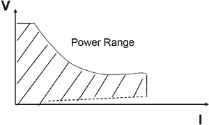
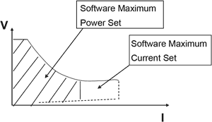
Executing Automatic Test FunctionPress the key Shift+0 to enter into the menu configuration, and then press the ▲ and ▼ keys to get the item MENU AUTO TEST, followed by pressing the Enter key to confirm. Then press the ▲ and ▼ keys to get the item LOAD AUTO TEST, followed by pressing the Enter key to confirm. Then press the ▲ and ▼ keys to select the sequential code defined as the automatic test function you want to execute, followed by pressing the Enter key to confirm. Then the upper right corner of the VFD display shows AUT n, meaning the n automatic test list will be initiated. The bottom right of the VFD. If users have prepared all things well, press the key On/Off to initiate the automatic test. The automatic test can also be initiated by lowering the voltage level of TRIG IN port and lasting more than 5mS. When in testing, the right lower corner of the VFD display will show WAIT or STAY, meaning waiting for testing or staying in the suspended mode respectively. Please retrigger it so that it goes on testing. After testing, the right lower corner of the VFD display will show either PASS or FAIL. When failure, the buzzer will sound. At this moment, initiate next trigger or press any key to free from the indication of pass or fail. When once automatic test is finished, users can press the ▲ and ▼ keys to initiate manually operated test mode. Every time press the key ▲ or the key ▼ once, the load will begin to the carrying test of the last step or the next step. Users can observe the actual state of every step. When the key ON/OFF is pressed or a trigger is input, the electronic load will automatically exit from the manually operated test mode and start to automatic test again. Input ControlShort Circuit Operation (SHORT)Load can simulate a short circuit at the input end by turning the load on with full-scale current. The short circuit can be toggled on/off at the front panel by pressing the key Shift+9 (Short). Short circuit operation does not influence the current value set. When short circuit operation is on OFF state, the Load will back to the original setting state. The actual current value that the load consumes in short circuit condition is dependent on the working mode and current range of the load that are active. In CC, CW and CR mode, the maximum short-circuit current value is 1.2 times of the current range. In CV mode, short-circuit operation is same as the operation of setting constant voltage to 0V. Input On/Off OperationWhen the load input state is in ON state, you can press the key On/Off to change the input state into OFF state. Then the right upper corner of the VFD display shows OFF. When the load input state is in OFF state, you can press the key On/Off to change the input state into ON state. Then the right upper corner of the VFD display shows ON indicating the current working state. Electronic Load Operation RangeElectronic load works in the range of Rated Current, Rated voltage and Rated Power. Please refer to the picture 4-13 and picture 4-14.
Electronic load Mode Change
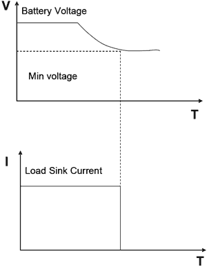
Protection FunctionsElectronic load includes the following protection functions. Over Voltage Protection (OV)If input voltage exceeds the voltage limit, load will turn off the input. Buzzer will sound and the VFD display shows Over Volt. The load maximum voltage value can be set by pressing the key Shift+0 (Menu). When the VFD display shows MENU SYSTEM SET, press the key Enter to confirm. Then the VFD display shows SYSTEM IMAX=xxxxxxxxA. Press the Up and Down keys to make adjustment until the VFD display shows SYSTEM UMAX=xxxxxxxxVindicating the current maximum voltage value, then enter the maximum voltage value required by pressing the numeric keys and decimal point key, followed by pressing the key Enter to confirm. Then press the key Esc to escape the Menu item. Besides, the maximum voltage value has close relation with the voltage resolution. If the maximum voltage value is below 20V, the load voltage resolution will be 0.1mV; if the maximum voltage value is beyond 20V, then the load voltage resolution will be only 1mV. Over Current Protection (OC)When input current exceeds the current limit, Buzzer will sound and VFD display will shows OVER CUR. The load maximum voltage value can be set by pressing the key Shift+0 (Menu). When the VFD display shows MENU SYSTEM SET, press the key Enter to confirm. Then the VFD display shows SYSTEM IMAX=xxxxxxxxA indicating the current maximum current value. Press the numeric keys and decimal point key to enter the maximum current value required, followed by pressing the key Enter to confirm. Then press the key Esc to escape the Menu item. Besides, the maximum current value has close relation with the current resolution. If the maximum current value is or is below 3A, the load current resolution will be 0.01mA; If the maximum current value is beyond 3A, then the load current resolution will be only 0.1mA. Over Power Protection (OW)When input power exceeds the power limit, buzzer will sound and VFD display will show OVER POW. Users need to press any key to get the load work normally. Note: if the current input state is in OFF state, you need to press the key ON/OFF to make the load work normally. If the over power problem is not solved, the load will shows OVER POW again. The load maximum power value can be set by pressing the key Shift+0 (Menu). When the VFD display shows MENU SYSTEM SET, press the key Enter to confirm. Then the VFD display shows SYSTEM IMAX=xxxxxxxxA. Press the Up and Down keys to make adjustment until the VFD display shows SYSTEM PMAX=xxxxxxxxW indicating the current maximum power value, then enter the maximum power value required by pressing the numeric keys and decimal point key, followed by pressing the key Enter to confirm. Then press the key Esc to escape the Menu item. Input Polarity ReversedWhen the electronic load is in input polarity reversed state, the buzzer will sound and the VFD display will show REVERSE Over Heat Protection (OH)If internal power component's temperature exceeds 80°C, over height protection will be initiated automatically. Load will turn off the input and Buzzer will sound and VFD display will show OVERHEAT. Remote Measurement FunctionWhen in CV, CR and CP mode, if load consumes high current, the power supplier will produce voltage drop in the connecting wire between measured power supplier and load terminals. In order to guarantee the measurement accuracy, remote measurement terminals is installed at the rear-panel of the electronic load. Users can measure the output terminals voltage of measured power supplier by these terminals. The remote measurement function can be set by pressing the key Shift+0 (Menu). When the VFD display shows MENU SYSTEM SET, press the key Enter to confirm. Then the VFD display shows SYSTEM IMAX=xxxxxxxxA. Press the Up and Down keys to make adjustment until the VFD display shows SYSTEM TERMINAL SEL indicating to set the parameters of the current remote measurement function, then press the key Enter to confirm. When the VFD display shows TERMINAL SELECT FRONT or TERMINAL SELECT BACK, press the Up and Down keys to select the parameters of remote measurement function. Showing TERMINAL SELECT FRONT means input terminals selected is at the front panel and the remote measurement function of the rear panel is closed; showing TERMINAL SELECT BACK means input terminals selected is at the rear panel and the remote measurement function of the front panel is closed. Then press the key Esc to escape the Menu item. Note: At any time either the input terminals at the front panel or at the back panel is initiated. It is impossible to initiate the input terminals both at the front panel and at the back panel together. If the voltage of the load is near to zero point and does not change according to the signal, please check if the wire mode matches the parameters of the remote measurement function. Battery TestingExperiment proves the test with load is the best method to ensure the battery whether work well or not. Only with the correct load testing, the battery can be confirmed if it was being the expectant life curve location. The electronic loads can be used to test any type of the battery nowadays. As to any battery used either in sheltered equipment or in the uninterrupted service system, it is necessary to use the load testing. Because the battery is the lowest reliable component, it must be tested by the load periodically to ensure the reliability of the battery. Capability TestConstant current mode is applied in electronic load to test the capability. A program is set to control voltage level. When the voltage of the battery is too low, the electronic load will identify the battery being on the threshold value set or at the margin of insecure state and will stop testing automatically. When the load is in testing procedure, you can see the battery voltage, battery discharge current, electronic, load power and battery capability that has been spared. If the load is connected with PC software, then you can see the discharge curve of battery discharge. This test can test out the reliability and remaining life of battery. So it is very necessary to do the test before you change another new battery. Operation:
Communication protocolIntroductionProgrammable electronic loads work with Modbus protocol. The data frame contains 4 parts as follows:
To make sure high reliability for the communication, we need to set the frame pitch greater than 3.5 times of the transient time of single bit byte. Eg. when the baud rate is 9600, then the frame pitch time must be greater than 11*3.5/9600=0.004s. Programmable electronic loads provided with double way asynchronous communication, fixed 1 bit as the start bit, 8 data bit, and 1 stop bit. Support Non parity check, Odd Parity check and even parity check. Baudrate could be selected as 2400, 9600, 14400, 28800, 57600, 115200. 1) Setup additional address and communication parameter The additional address is a single byte with 16 hexadecimal system data; electronic loads will only response the request data frame which has the same additional address. 2) Setup the additional address Press Shift+0 in turn, Enter into the Main Menu, the Load will display as MENU CONFIG,Press the key Enter to confirm, then the load get into CONFIG Menu, press ▲ and ▼ key button, to let the load display CONFIG ADDRESS SET, then press Enter to confirm, the load will display ADDRESS ADDR= xxx, you can change the address number by press the numeric keys, and press the key Enter again to confirm. Note: The valid additional address number is integers in the range of 1-200. 3) Select the check mode Press Shift+0 in turn, enter into the main Menu, the load will display MENU CONFIG, press the key Enter to confirm,the load will get into CONFIG menu, press ▲ and ▼ key button, to let the load display CONFIG COMM.PARITY, press Enter to confirm, then the load will display COMM.PAR xxxxx, you can select the parity check mode by pressing ▲ and ▼ key button, and then press Enter to confirm. Setup BaudratePress Shift+0 in turn, the load will display MENU CONFIG, Press Enter to confirm, the load will enter into CONFIG menu, press ▲ and ▼ key button to let the load display CONFIG BAUDRATE SET, press Enter to confirm, the load will display BUADRATE xxxxx, you can choose the appropriate baudrate as you need, and press Enter to confirm. Totally 6 different baudrate provided for selection. 2400, 9600, 14400, 28800, 57600, 115200. DataIn some data frame, the date length is fixed, but there are some data frame length is not fixed. According to Modbus protocol, in the data field, all the hex data and floating point number are formed as the High Byte in the former and Low byte in the after. Addition,the output value of force single coil must be 0x0000 or 0xFF00. 0x0000 means OFF, while 0xFF00 means ON. All other values are invalid and will not affect the coil. Function CodeFunction codes are single byte hex number; there are 4 function modes as follows:
Error checking (CRC)Programmable electronic loads use the Cyclic Redundancy Check (CRC). The CRC field checks the contents of the entire message. The CRC fileld is two bytes, containing a 16-bit binary value.When the CRC ia appended to the message, the low-order byte is appended first, followed by the high-order byte. The discipline is as follows:
Complete Command Frame Analysis1. Read Coil Status (0x01) Read Coil Status Example Query
Read Coil Status Example Normal Response
Read Coil Status Example Abnormal Response
For example: The following example reads the load input state (ISTATE) of Coil at slave device address 0x01. From table "Coil-bit definition" we know that the ISTATE address is 0x0510. Query: 0x01 0x01 0x05 0x10 0x00 0x01 0xFC 0xC3 The Corresponding Nomal Response: 0x01 0x01 0x01 0x48 0x51 0xBE, among which, 0x48 is the read-back data and its lowest bit is 0, this means the input state ISTATE is OFF. 2. Force Single Coil (0x05) Force Single Coil Example Query
Force Single Coil Example Normal Response
Force Single Coil Example Abnormal Response
A value of 0xFF00 forces the coil to be ON, and 0x0000 forces the coil to be turned OFF. All other values are invalid and will not affect the coil. For example: The following example sets the load is in remote control at slave device address 0x01. From table "Coil-bit definition" we know that the PC1 remote address is 0x0510. Query: 0x01 0x05 0x05 0x00 0xFF 0x00 0x8C 0xF6 The Correponding Response: 0x01 0x05 0x05 0x00 0xFF 0x00 0x8C 0xF6 3. Read Holding Registers (0x03) Read Holding Registers Example Query
Read Holding Registers Example Nomal Response
Read Holding Registers Example Abnormal Response
For example: The following example reads the present voltage value at slave device address 0x01. From table "Coil-bit definition" we know that the register address of the present voltage value is 0x0B00, Query: 0x01 0x03 0x0B 0x00 0x00 0x02 0xC6 0x2F The Corresponding Nomal Response: 0x01 0x03 0x04 0x41 0x20 0x00 0x2A 0x6E 0x1A, among which, 0x41 0x20 0x00 0x2A is the read-back voltage value, the corresponding floating point number is 10V. 4. Preset Multiple Registers (0x10) Preset Multiple Registes Example Query
Preset Multiple Registers Example Response
Preset Multiple Registers Example Abnormal Response
For example: The following example sets the load's constant current IFIX is 2.3A at slave device address 0x01. From table "Register XRAM area definition" we know that the IFIX register address is 0x0A01, the floating point takes up two-word length. Query: 0x01 0x10 0x0A 0x01 0x00 0x02 0x04 0x40 0x13 0x33 0x33 0xFC 0x23 The Corresponding Normal Response: 0x01 0x10 0x0A 0x01 0x00 0x02 0x13 0xD0 Coil With The Register Address AllocationTable 1: Coil-bit definition
Table 2: Register XRAM area definition
The Definition Of The Command Register CMD
Common Operation Function DescriptionTable 1 Remote Control Operation
Table 2 cancel remote control operation
Table 3 Local Prohibition control operations
Table 4 Local allows the operator to
Table 5 Input ON operation
Table 6 Input OFF operation
Table 7 Short-circuit operation
Table 8 CC mode operation
Table 9 CV mode operation
Table 10 CW mode operation
Table 11 CR mode operation
Table 12 CC mode soft-start
Table 13 CV mode soft-start
Table 14 CC loading and unloading mode
Table 15 CV loading and unloading mode
Table 16 CW loading and unloading mode
Table 17 CR loading and unloading mode
Table 18 CC mode switch to CV mode
Table 19 CR mode switch to CR mode
Table 20 battery test mode
Table 21 Dynamic Test Mode
Table 22 System parameter setting mode
Frequently Asked Questions
Compatible Software
Back to the section |
||||||||||||||||||||||||||||||||||||||||||||||||||||||||||||||||||||||||||||||||||||||||||||||||||||||||||||||||||||||||||||||||||||||||||||||||||||||||||||||||||||||||||||||||||||||||||||||||||||||||||||||||||||||||||||||||||||||||||||||||||||||||||||||||||||||||||||||||||||||||||||||||||||||||||||||||||||||||||||||||||||||||||||||||||||||||||||||||||||||||||||||||||||||||||||||||||||||||||||||||||||||||||||||||||||||||||||||||||||||||||||||||||||||||||||||||||||||||||||||||||||||||||||||||||||||||||||||||||||||||||||||||||||||||||||||||||||||||||||||||||||||||||||||||||||||||||||||||||||||||||||||||||||||||||||||||||||||||||||||||||||||||||||||||||||||||||||||||||||||||||||||||||||||||||||||||||||||||||||||||||||||||||||||||||||||||||||||||||||||||||||||||||||||||||||||||||||||||||||||||||||||||||||||||||||||||||||||||||||||||||||||||||||||||||||||||||||||||||||||||||||||||||||||||||||||||||||||||||||||||||||||||||||||||||||||||||||||||||||||||||||||||||||||||||||||||||||||||||||||