|
||||
|
|
|||
|
||||
|
|
|||
|
Search
Log in
|
AM-7111 Process Calibrator
AKTAKOM AM-7111 multifunctional process calibrators are designed to generate high-precision signals when testing and calibrating different types of equipment (probes, measurers, converters, controllers etc.) during repair or adjustment work. These compact handheld devices are necessary for service engineers, they save time and solve a wide range of tasks in field conditions. Specifications
Standard accessories:
Sourcing DC Voltage
Step 1: Using V key to select DC voltage source function, select the desired range from 100mV, 1000mV, and 10V by pressing the RANG key. The default value and unit of the selected source function and range shall be displayed in the main districts part of the LCD. Step 2: Set the output value digit by digit using ▲ / ▼ keys. Each pair of ▲ / ▼ keys corresponds to each digit of the LCD reading. Each press of ▲ / ▼ key increases or decreases the digit. Increasing the digit from 9 or decreasing it from 0 causes the digit to overflow or underflow, allowing you to set the output value without interruption. Holding down the ▲ / ▼ keys continuously changes the digit in question. And the value won’t change if it is increased or decreased to the Maxim or Minimum value. Pressing ZERO key initializes the output set point to the default value (0). Step 4: To turn off the output, press the ON key once again. OFF appears on the LCD and no signals sourced between the terminals.
Sourcing DC Current
Step 1: Using mA key to select the desired source function 0-22mA .The default value and unit of the selected source function shall be displayed in the main districts part of the LCD. Step 2: Set the output value digit by digit using ▲ / ▼ keys. Each pair of ▲ / ▼ keys corresponds to each digit of the LCD reading. Each press of the ▲ / ▼ key increases or decreases the digit. Increasing the digit from 9 or decreasing it from 0 causes the digit to overflow or underflow, allowing you to set the output value without interruption. Holding down ▲ / ▼ key continuously changes the digit in question. And the value won’t change if it is increased or decreased to the Maxim or Minimum value. Pressing the ZERO key initializes the output set point to the default value (0). Step 3: Pressing ON key causes the indicator on the LCD to change from OFF to ON. The calibrator sources the preset DC current between the output terminals. Step 4: To turn off the output, press ON key once again. OFF appears on the LCD and no signals sourced between the terminals.
Sourcing Resistance
Step 1: Using the OHM key, select Ohm function. Using the RANGE key, select the desired range. The selected function and the default range source value and unit shall be shown in the main districts part of the LCD. Step 2: Set the output value digit by digit using each pair of ▲ / ▼ keys. Each pair of ▲ / ▼ keys corresponds to each digit of the LCD reading. Each press of the ▲ / ▼ key increases or decreases the digit. Increasing the digit from 9 or decreasing it from 0 causes the digit to overflow or underflow, allowing you to set the output value without interruption. Holding down the ▲ / ▼ key continuously changes the digit in question. And the value won’t change if it is increased or decreased to the Maxim or Minimum value. Pressing the ZERO key initializes the output set point to the default value (0). Step 3: Pressing the ON key causes the SOURCE indicator on the LCD to change from OFF to ON. The calibrator sources the preset resistance value between the output terminals.
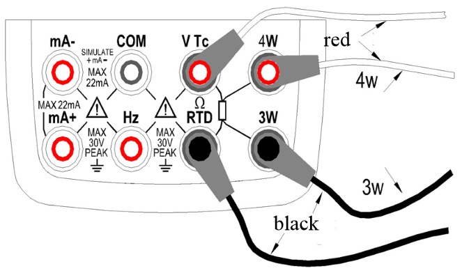
Step 4: To turn off the output, press the ON key once again. The OFF appears on the LCD and no signals sourced between the terminals. The connection method based on three-wire and four-wire is shown in the below picture:
Simulate Sourcing TC
The calibrator is designed with an internal temperature sensor. To calibrate a device with built-in reference junction temperature compensation by sourcing a thermoelectromotive force with the calibrator without using non-external 0C reference junction compensation means, use the RJ sensor function. Select simulate TC source function, in which RJ senor goes on work automatically. The “RJ-ON” mark displays on the middle part of the screen. Step 1: Using the Tc key, select simulate TC source function. Using the RANGE key, select the desired range from K, E, J, T, B, N, R, S, L, U. The selected function and the default range source value and unit shall be shown in the main districts part of the LCD. Step 2: Set the output value digit by digit using each pair of ▲ / ▼ keys. Each press of ▲ / ▼ key increases or decreases the digit. Increasing the digit from 9 or decreasing it from 0 causes the digit to overflow or underflow, allowing you to set the output value without interruption. Holding down ▲ / ▼ key continuously changes the digit in question. And the value won’t change if it is increased or decreased to the Max. or Min. value. Pressing the ZERO key initializes the output set point to the default value (the default value of a typical B type is 600°C). Step 3: Pressing ON key causes the SOURCE indicator on the LCD to change from OFF to ON. A thermoelectromotive force based on the temperature detected by the RJ sensor develops between the output terminals. Step 4: To turn off the output press ON key once again. OFF appears on the LCD and no signals sourced between the terminals. Note: If you don’t need the reference junction compensation, press the RJ-ON key to shut off. The calibrator source a value with using external 0°C reference junction compensation means, and the RJ-ON mark vanishes. Press the RJ-ON key once more to start the reference junction compensation and the RJ-ON mark displays in the middle of the screen. Simulate Sourcing RTD
Step 1: Using the RTD key, select RTD function. Using the RANGE key, select a desired RTD range from PT100, PT200, PT500, PT1000, Cu10, Cu50. The selected function and the default range source value and unit shall be shown in the main districts part of the LCD. Types of RTD shall be shown in the middle part of the LCD. Step 2: Set the output value digit by digit using each pair of ▲ / ▼ keys. Each press of ▲ / ▼ key increases or decreases the digit. Increasing the digit from 9 or decreasing it from 0 causes the digit to overflow or underflow, allowing you to set the output value without interruption. Holding down the ▲ / ▼ key continuously changes the digit in question. And the value won’t change if it is increased or decreased to the Maxim or Minimum value. Pressing the ZERO key initializes the output set point to the default value (0). Step 3: Pressing ON key causes SOURCE indicator on the LCD to change from OFF to ON. The calibrator sources the preset resistance value between the output terminals. Step 4: To turn off the output, press ON key once again. The OFF appears on the LCD and no signals sourced between the terminals. Sourcing Frequency
The calibrator can source a constant pulse signal responding to the preset frequency and amplitude. Step 1: Using Step 2: Using RANG key, select a desired frequency range from 100Hz, 1KHz,10kHz,100KHz. The selected function and the default range source value and unit shall be shown in the LCD. Step 3: Set the output value digit by digit using each pair of ▲ / ▼ output setting keys. Each pair of ▲ / ▼ keys corresponds to each digit of the LCD reading. Each press of ▲ / ▼ key increases or decreases the digit. Increasing the digit from 9 or decreasing it from 0 causes the digit to overflow or underflow, allowing you to set the output value without interruption. Holding down ▲ / ▼ key continuously changes the digit. And the value won’t change if it is increased or decreased to the Maxim or Minimum value. Step 4: Pressing the Vpeak key once switches to amplitude setting mode. The LCD provides a reading of 1V. Step 5: Set the output value digit by digit using each pair of ▲ / ▼ output setting keys. Each pair of ▲ / ▼ keys corresponds to each digit of the LCD reading. Each press of ▲ / ▼ key increases or decreases the digit. Increasing the digit from 9 or decreasing it from 0 causes the digit to overflow or underflow, allowing you to set the output value without interruption. Holding down ▲ / ▼ key continuously changes the digit. And the value won't change if it is increased or decreased to the Max. or Min. value. Step 6: To re-enter into the frequency set mode, press the FREQ key to set the frequency. Step 7: Pressing ON key causes the SOURCE indicator on the LCD to change from OFF to ON. The calibrator sources constant pulse signals responding to the preset frequency and amplitude between the output terminals. Step 8: To turn off the output, press ON key once again. The OFF appears on the LCD and no signals sourced between the terminals. Sourcing Number of Pulses
The calibrator can source a preset number of pulse signal responding to the preset frequency and amplitude. Step 1: Using Step 2: Using the RANGE key, select a desired frequency range from 100Hz, 1KHz, 10kHz. The selected function and the default range source value and unit shall be shown in the LCD. Step 3: Set the output value digit by digit using each pair of ▲ / ▼ output setting keys. Each pair of ▲ / ▼ keys corresponds to each digit of the LCD reading. Each press of ▲ / ▼ key increases or decreases the digit. Increasing the digit from 9 or decreasing it from 0 causes the digit to overflow or underflow, allowing you to set the output value without interruption. Holding down ▲ / ▼ key continuously changes the digit . And the value won’t change if it is increased or decreased to the Maxim or Minimum value. Step 4: Pressing the Vpeak key once switches to amplitude setting mode. The LCD provides a reading of 1V. Step 5: Set the output value digit by digit using each pair of ▲ / ▼ output setting keys. Each pair of ▲ / ▼ keys corresponds to each digit of the LCD reading. Each press of ▲ / ▼ key increases or decreases the digit. Increasing the digit from 9 or decreasing it from 0 causes the digit to overflow or underflow, allowing you to set the output value without interruption. Holding down ▲ / ▼ key continuously changes the digit. And the value won't change if it is increased or decreased to the Max. or Min. value. Step 6: Pressing CYC key ,enter into the pulse number set mode, and the LCD shows the default number of 1 CYC. Step 7: Set the output value digit by digit using each pair of ▲ / ▼ output setting keys. Each pair of ▲ / ▼ keys corresponds to each digit of the LCD reading. Each press of ▲ / ▼ key increases or decreases the digit. Increasing the digit from 9 or decreasing it from 0 causes the digit to overflow or underflow, allowing you to set the output value without interruption. Holding down ▲ / ▼ key continuously changes the digit. And the value won't change if it is increased or decreased to the Max. or Min. value. Step 8: To re-enter into the frequency set mode, press FREQ key to set the frequency. Step 9: Pressing ON key causes the SOURCE indicator on the LCD to change from OFF to ON, and the calibrator sources low level between the output terminals. Step 10: Pressing START key the calibrator sources the set number of pulse responding to the preset frequency and amplitude, LCD shows the symbol RUN. Step 11: When source is complete, the calibrator automatically turns off the output and ceases operation. RUN symbol disappears from the LCD. Step 12: To turn off the output, press ON key once again. OFF appears on the LCD and no signals sourced between the terminals. Sourcing Switch
You can turn on or off the output terminals by using the contact output function. An FET is used as the contact-switching device. Step 1: Using Step 2: Using RANGE key select the desired frequency from 100Hz, 1KHz, 10 KHz and 100KHz. The LCD shows the default value and unit. Step 3: Set the output value digit by digit using each pair of ▲ / ▼ output setting keys. Each pair of ▲ / ▼ keys corresponds to each digit of the LCD reading. Each press of ▲ / ▼ key increases or decreases the digit. Increasing the digit from 9 or decreasing it from 0 causes the digit to overflow or underflow, allowing you to set the output value without interruption. Holding down ▲ / ▼ key continuously changes the digit. And the value won’t change if it is increased or decreased to the Max. or Min. value. Step 4: Pressing ON key causes the SOURCE indicator on the LCD to change from OFF to ON and the calibrator sources contact signals responding to the present frequency. Step 5: To turn off the output, press ON key once again. The OFF appears on the LCD and no signals sourced between the terminals. Zero-off function
In any range of DC voltage, DC current, ohm, TC and RTD functions, pressing ZERO key selects clearing off function which initializes the preset source value for the convenience of user to reset source value. In frequency, pulse, contact output functions ZERO key is unavailable. Frequently Asked Questions
Back to the section |
||||||||||||||||||||||||||||||||||||||||||||||||||||||||||||||||||||||||||||||||||||||||||||||||||||||||||||||||||||||||||||||||