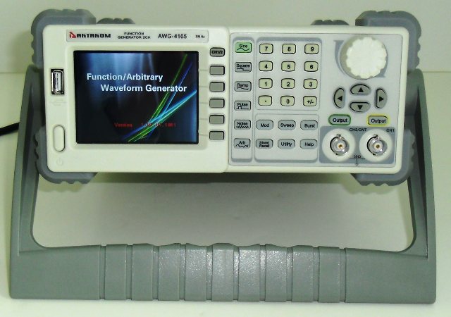
Test equipment applications require signal stimuli varying from advanced communication signals to the playback of captured real-world analog signals. Signal source instruments generate the signal stimulus that is applied to a device under test (DUT). Consequently, signal sources comprise an important class of test instruments. AKTAKOM AWG-4105, AWG-4110 and AWG-4150 Series Function/Arbitrary Waveform Generators adopt the direct digital synthesis (DDS) technology, which can provide stable, high-precision, pure and low distortion signals. Its combination of excellent system features, easiness in usage and versatile functions makes this generator a perfect solution for your job now and in the future.
There is a general market consensus on the naming conventions for signal, function and waveform generators. A signal generator provides a high-fidelity sine wave signal ranging from low frequencies to many GHz. Attenuation, modulation, and sweeping are typical features of a signal generator. A function generator is a lower-frequency instrument that provides sine, square, pulse, triangle and ramp waveforms. Function generators in general provide these standard functions from DC to a few MHz, and typically provide large voltage ranges. AKTAKOM arbitrary waveform generator is a highly flexible signal source that generates any arbitrary waveform that has been constructed point-by-point in digital memory. The constructed waveform is converted to an analog signal using a digital-to-analog converter (DAC) operating at clock rates up to a design frecuency. The built-in AM, FM, PM, ASK, and FSK modulation functions generate modulated waveforms at ease, without the help of a separate modulating source. USB I/O is a standard accessory, while LAN and GPIB are optional. Remote instructions meet the SCPI specification requirements.
Standard Functions
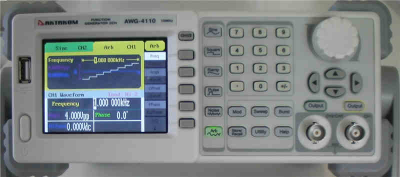
Standard functions include the sine, square, pulse, triangle, and ramp waveforms that are commonly used in applications such as the testing of baseband, audio, sonar, ultrasound, and video components and circuits. Some tests that can be performed with standard function waveforms include frequency response characterization, device linearity characterization, digital logic generation, and DC-offset signal generation. The frequency response of a device under test (DUT) can be characterized by waveform responses
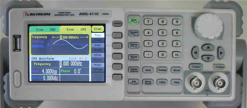
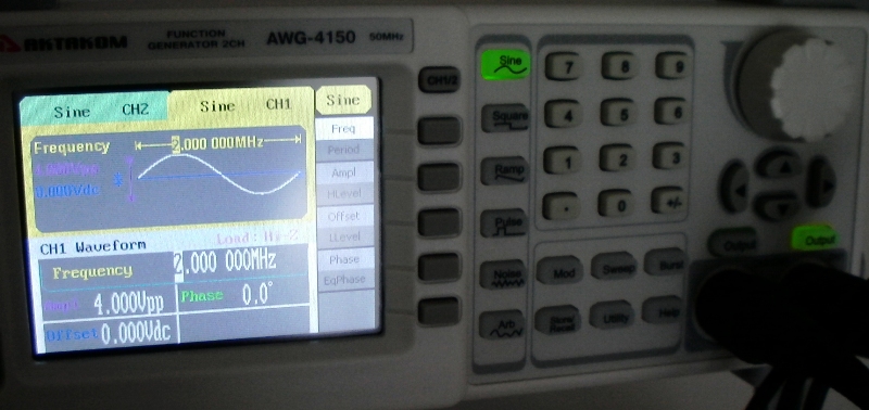
Sine
Square
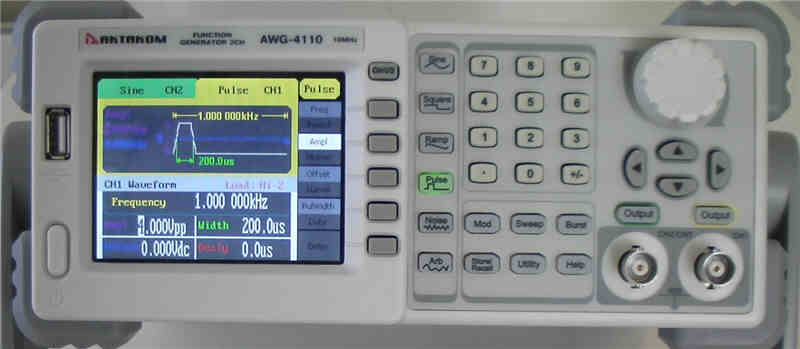
Pulse
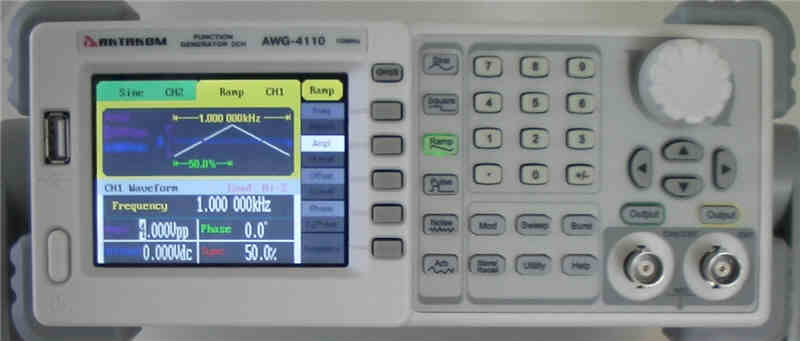
Ramp
Arbitrary Waveforms
Arbitrary waveforms involve the point-by-point user-defined waveform synthesis. This provides unlimited flexibility to the user to create custom waveforms.
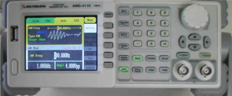
Modulate
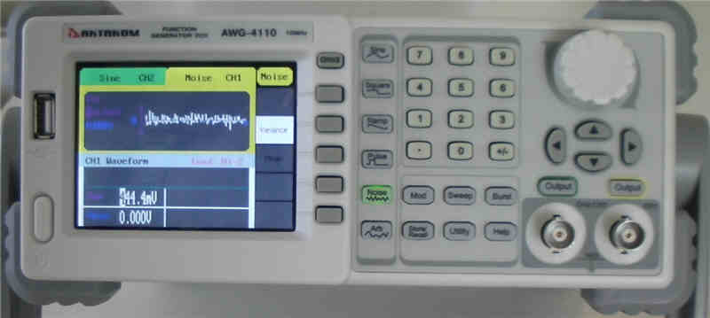
The modulated waveform can be changed by modifying the parameters such as type, internal/external modulation, depth, frequency, waveform, etc. AWG Series can modulate waveform using AM, FM, PM, ASK and FSK. Sine, square, ramp or arbitrary waveforms can be modulated (pulse, noise and DC can not be modulated).
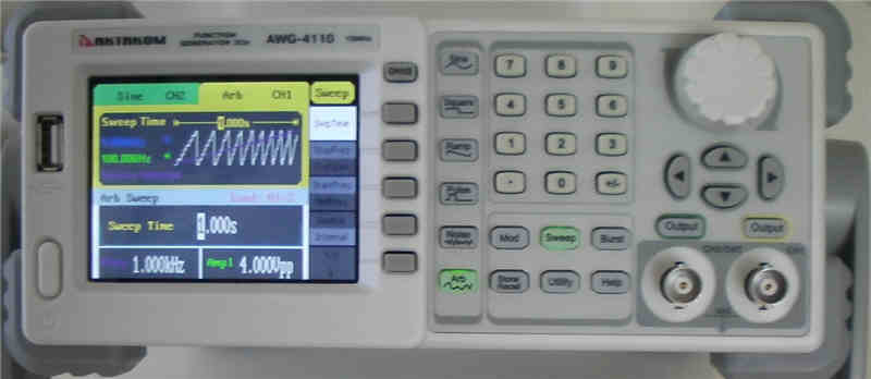
Sweep
Pressing Sweep button, sine, square, ramp or arbitrary waveform can be swept (pulse, noise and DC can not be swept). In the sweep mode, AWG Series generate signal with variable frequencies.
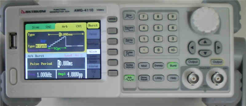
Burst
Pressing Burst button, burst for sine, square, ramp, pulse or arbitrary waveform can be generated. Output waveforms with set cycle times. Burst can last for certain times of waveform cycle (N-Cycle Burst) or be controlled by external gated signals (Gated Burst). Burst applies to all kinds of waveforms, but noise can only be used in gated burst. Generally it is called burst function within every signal generator.
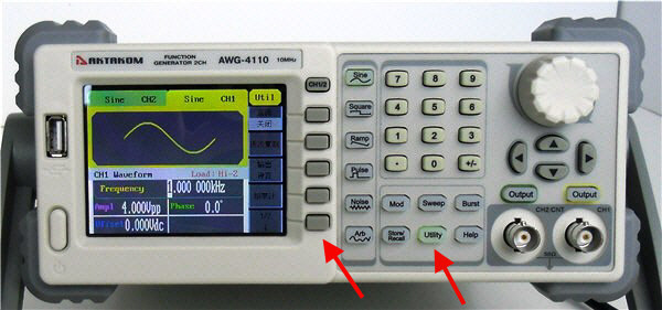
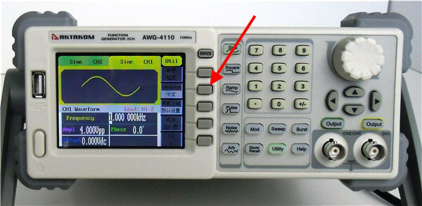
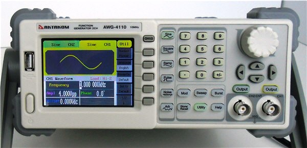
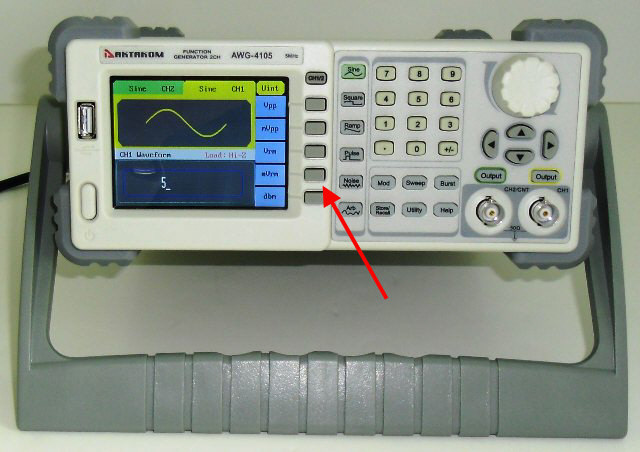
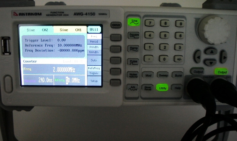
AWG Series have included a frequency counter. How to use it?
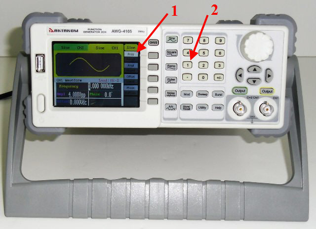
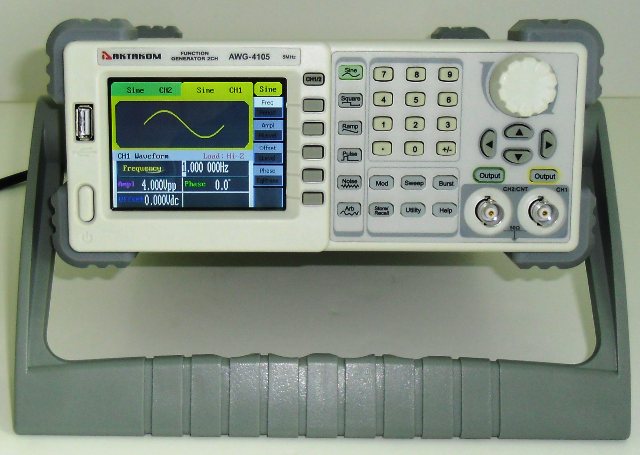
AWG Series have included a frequency counter which could measure frequency from 100mHZ to 200MHZ under CH2/CNT utility regime. For testing purpose you may connect CH1 and CH2 using a BNC cable.
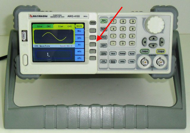
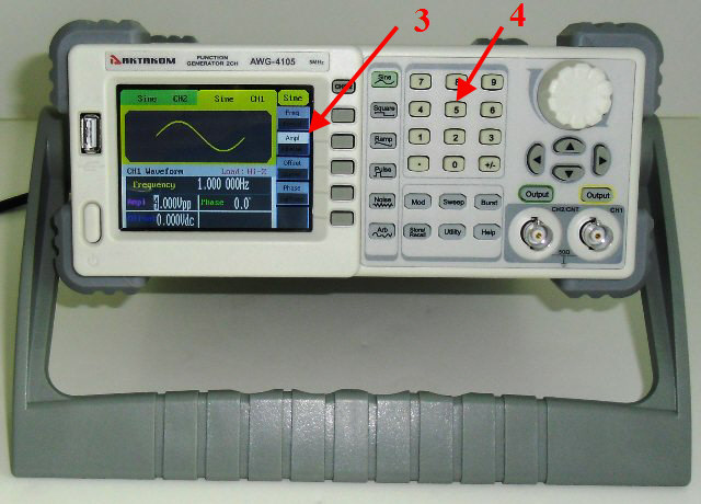
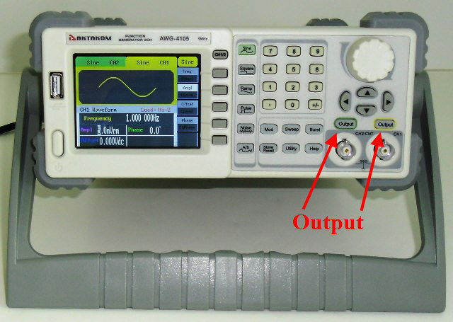
Set any signal at CH1 with any frequency and press the Output button.
Now at CH2 (please press CH1/2 button) press button Utility and then following the column down press the button at the right of Counter. You will see the value of the frequency you programmed at CH1 immediately.