Search
Log in
Login:
Password:
Register
Forgot your password?

ADS-4072 Handheld Digital Oscilloscope

3-in-1: Oscilloscope + DMM + Datalogger. Oscilloscope: bandwidth 70 MHz, 2 channels, max sampling rate 1 GSa/s, record length 240 Kpts, vertical resolution 8 bit, volts/div range 5 mV/div - 50 V/div, time base range 4 ns/div - 10 s/div, 31 automatic measurements, cursor measurements, serial bus trigger (UART, LIN, CAN, SPI, I²C, MIL-STD-1553B, ARINC429), FFT. DMM: voltage (AC, DC, AC+DC), current (AC, DC), resistance, capacitance, continuity check, diode check; statistics (max., min., average), relative measurements. USB Device, USB Host, colour touch screen 5,6" (640x480), battery (7,4 V/6000 mAh). Dimensions 254 x 160 x 60 mm / 10 inches x 6.3 inches x 2.4 inches, weight 1,4 kg / 3 pounds

Manuals: 
User's Manual (2.31 Mb)

New AKTAKOM ADS-4072 Handheld Digital Oscilloscope is 3-in-1 meaning it combines oscilloscope, DMM and datalogger functions. It can be used for different measurement tasks connected with field test, service support. This model is perfect for the use in research laboratories and educational institutions. New oscilloscopes have such advantages and innovative technical features which do not pertain to some other well-known brands.

Features

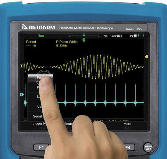
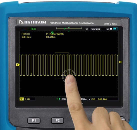
  • Three operation modes for moving waveform, zooming in and out, and using menu by touch, button and scroll wheel

  • 5.6" TFT LCD touch screen, 640 * 480 high resolution

  • Memory depth: 240 Kpts
  • Waveform capture rate: up to 190 000 wfms/s

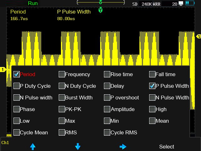
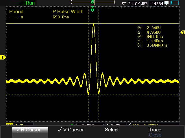
  • Auto (23 types) and cursor measurements in oscilloscope mode

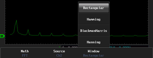
  • Math operation (*, /, -, +) and FFT window settings (4 windows)

  • Trigger type: edge, pulse, logic, serial bus (UART,LIN,CAN,SPI,I2C)

  • 3 types of record modes: multimeter record, oscilloscope measurement record and oscilloscope waveform record

  • Shockproof housing
  • Weight 1,4 kg / 3 pounds

Specifications:

Vertical system:

  • Channels: 2 oscilloscope channels,1 multimeter channel
  • Limited bandwidth: 20MHz
  • Coupling modes: DC,AC,GND
  • Input impedance: parallel 1MΩ±1% with 15pF±3pF
  • Vertical scale: 5mV/div~50V/div
  • Vertical resolution: 8 bits
  • DC vertical gain accuracy: 5mV/div~50V/div,2.0%

Horizontal system:

  • Timebase: 4ns/div~10s/div
  • Timebase delay range: -12divs~50s
  • Timebase accuracy: 20ppm
  • Sample mode: normal,average, pk-pk,envelope
  • Dynamic record: - (can be upgraded)
  • Store waveform: 4 ref waveforms (can be upgraded to flash disk storage)

Trigger system:

  • Trigger types: edge, pulse, logic, serial bus(UART,LIN,CAN,SPI,I2C)
  • Trigger coupling: DC,AC,High-frequency suppression,Low-frequency suppression, Noise suppression
  • Trigger modes: auto, normal, single
  • Trigger scource: CH1,CH2
  • Inhibition range: 200ns~10s

Math:

  • Operator: + , - , * , /
  • FFT window settings: Rectangular, Hamming, Blackman-Harris, Hanning

DMM:

  • Measurement types: 9 physical measurements such as voltage, current, resistance, capacitance, diode , etc.
  • Measuremet accuracy: 4 bits
  • Measurement display: max, average, min, values with time stamp,relative measurement

Datalogger:

  • Logger content: multimeter measurements, oscilloscope waveform, oscilloscope measurements
  • Logger timebase: multimeter measurements,10s/div ~ 20min/div; oscilloscope measurements 10s/div ~ 20min/div
    oscilloscope waveform 100us/div ~ 2min/div
  • Logger time length: max 17 days

Power:

  • Power adapter: input:100-240VAC,50-60Hz,2A; output:12VDC,5A
  • Battery: capacity: 7.4V/6000mAh, work time:4~5 hours

Frequently Asked Questions

  • After the oscilloscope is powered on the display remains dark, what should I do?
  • There is wave form displayed, but it is not stable
  • When changing the horizontal sweep on the digital oscilloscope at different horizontal points observed inexplicable change in the form of the same signal, why is this happening?

  • After the oscilloscope is powered on the display remains dark, what should I do?

    Please implement the following fault treatment procedure.

    • Check whether the power cable is connected properly.
    • Ensure the power switch is turned on.
    • Restart the instrument after completing the checks above.
    • If the oscilloscope still can not work normally, please call for service.

    Up

    There is wave form displayed, but it is not stable
    • Check whether the Source item in the TRIG MODE menu is in conformity with the signal channel used in the practical application.
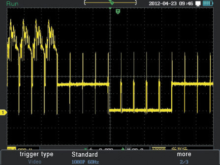
    • Check on the trigger Type item: The common signal chooses the Edge trigger mode for Type and the video signal the Video. Only if a proper trigger mode is applied, the wave form can be displayed steadily.
    • Try to change the trigger coupling into the high frequency suppress and the low frequency suppress to smooth the high frequency or low frequency noise triggered by the interference.

    Up

    When changing the horizontal sweep on the digital oscilloscope at different horizontal points observed inexplicable change in the form of the same signal, why is this happening?

    In fact, this is not a problem.

    Just keep in mind that you're using a digital oscilloscope, which digitizes the signal with different sampling rates depending on the selected horizontal sweep, and then connects the digitized points with strait line while restoring the real shape of the signal.

    Your first screen shows that you are measuring voltage 50 Hz with the 10 ms / div sweep and a sampling frequency of 20 kHz Ks/s

    One signal period (20 ms), digitized in this mode, 20E-03 (sec) * 20E03 (1/sec) = 400 points. This is enough to properly restore and interpolate a sine wave of 50 Hz (i.e. in a period of 20 ms).

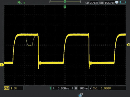
    Normal display, with a sweep 10 ms / div:

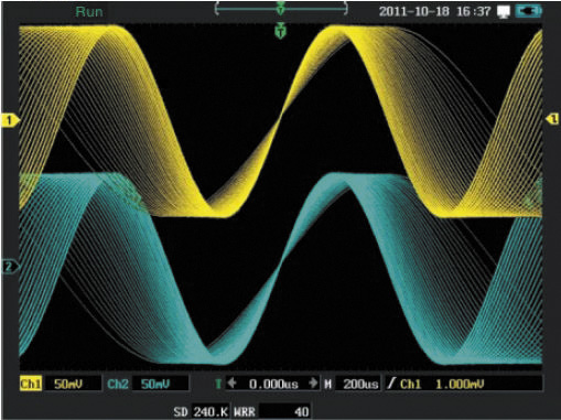
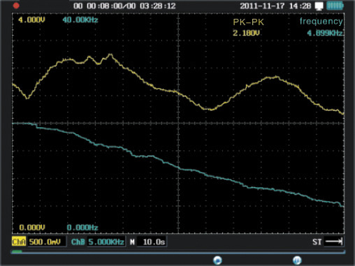
    Distortion of the same signal at 10 s / div sweep

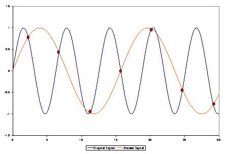
    Your second screen is set to sweep 10 sec / div, and sample rate on a sweep turned to 20 samples per second (20 Sa / s). I.e. one signal period 20 ms had: 20E-03 (sec) * 20 (1/sec) = 0.4 points. That means that to restore (to interpolate the points) a sine wave with less than one point in time is impossible, so you get this mess (known as "aliasing" or a false frequency) formed by the beats of the measured frequency and sampling frequency.

    In order to correctly install a data collection in a digital oscilloscope one should follow a simple rule - the sampling rate must be at least 5-10 times higher than the frequency signal, in that case you will not have the issues that we just discussed.

    This applies to all digital oscilloscopes and in no way connected to any particular make or model of oscilloscope or its probes.


    Up

    Handheld digital oscilloscopes AKTAKOM ADS-4000 series


    Back to the section