|
|
ADS-4062 Handheld Digital Oscilloscope
ADS-4062 Handheld Digital Oscilloscope
|
|
Dual channel. Bandwidth: 60MHz; Max. Sample rate: 1GSa/s (500MSa/s each channel); Max. Memory Depth: 2Mpts; Waveform math: +, -, ×, /, FFT; Trigger types: Edge, Video, Pulse, Slope, Alternate; 32 types Automatic measurement; Rise Time: ≤5.8ns; Time Base Range: 5ns/div…50s/div; Scan Range: 100ms/div…50s/div; Vertical Sensitivity: 2mV/div…100V/div; Vertical Resolution: 8bits; Frequency Counter: 6bits; Oscilloscope Trend Plot: 800kpts; Multimeter Trend Plot: 1.2Mpts; Recorder: 7Mpts. Built-in Frequency Counter. Built-in Multimeter: measurement voltage (AC, DC), current (AC, DC), resistance, capacitance, diode test, continuity test. 5.7” color TFT LCD display; USB device, USB host, Power Supply: 100...240VAC, battery; Dimensions: 10.2x6.4x2.1in / 259.5x163.2x53.3mm; Weight: 3.3lb/1.5kg.
Manuals:
|
|
AKTAKOM ADS-4062 is a high performance handheld oscilloscope with great range of dynamic input scope. It has small volume which convenient to carry, compact interface and etc. It satisfies the most needs of outside measurement and improves working efficiency greatly.
Features:
- Dual-input, combine oscilloscope, Multimeter and recorder (including TrendPlot and waveform Recorder) in one unit
- Input voltage: input voltage through BNC is up to CATII 300V and CATⅢ 150V
Standard probe: 10X CATII 400V
Optional probe: 10X CATII 1000V and 10X CATIII 600V
Oscilloscope and multimeter safety grade is up to CATII 600V and CATIII 300V
- 5.7 inch TFT color LCD display
- 60MHz Bandwidth, 1GSa/s real-time sampling rate single channel, up to 50GSa/s equivalent sampling rate, 2Mpts memory depth
- With 6000 dots display resolution Multimeter and provides measurements of DCV, ACV, DCI, ACI, Resistance, Diode, Capacitance and Continuity
- Support Scope TrendPlot, Meter TrendPlot and Scope Recorder
- Trigger modes: Automatic, Normal and Single
Trigger types: Edge, Pulse, Video, Slope and Alternative
- 32 automatic measurements, 3 cursor measure modes
- 4 digital filter mode: Low pass, High pass, Band pass, Band limit
- Math functions: +, - , ×, ÷, FFT operations
- Multiple Language User Interface
- Standard configuration interface: USB Device, USB Host
- Support USB storage and update; support PC remote control and PictBridge print
- Rechargeable Li battery pack, compact, portable, fit for outdoor operation
Oscilloscope Specifications:
|
Inputs System
|
|
Input Coupling
|
AC, DC, GND
|
|
Input Impedance
|
1MΩ±2% || 18pf±3pf
|
|
Probe Attenuator
|
1X, 10X
|
|
Voltage Probe Attenuator Factors
|
1X, 5X, 10X, 50X, 100X, 500X, 1000X
|
|
Current Probe Attenuator Factors
|
1X, 5X, 10X, 50X, 100X, 500X, 1000X
|
BNC Maximal Input Voltages
(refer to BNC crust)
|
Overvoltage Classes
|
|
CAT II
|
300Vrms
|
|
CAT III
|
150Vrms
|
|
Probe
|
Overvoltage Classes
|
Maximal Voltages
|
|
Standard Probe 10X
|
CAT II
|
400Vrms
|
|
Optional Probe 10X
|
CAT III
|
600Vrms
|
|
Multimeter Floating Voltages
|
Overvoltage Classes
|
Maximal Voltages
|
|
CAT II
|
600Vrms
|
|
CAT III
|
300Vrms
|
|
Channel Common Mode Rejection
|
>100:1 50MHz
|
|
Isolation Degree between Channels
|
>35dB
|
|
Acquisition System
|
|
Sample Types
|
Real time, Equivalent time
|
|
Memory Depth
|
Single Channel 32k, double channels 16K
|
|
Channel Mode
|
Sampling Rat
|
Common Storage
|
Deep Storage
|
|
Single Channel
|
1Gsa/s
|
40kpts
|
Don’t support
|
|
Single Channel
|
500MSa/s or below
|
20kpts
|
2Mpts
|
|
Double Channels
|
500MSa/s or below
|
20kpts
|
1Mpts
|
|
Sample Mode
|
Sample, Peak Measure, Average
|
|
Averages
|
4, 16, 32, 64, 128, 256
|
|
Vertical System
|
|
Vertical Sensitivity
|
2mV/div…100V/div (1-2-5 order)
|
|
Channel Voltage Offset Rang
|
2mV…200mV: ±1.6V
206mV…10V: ±40V
10.2V…100V: ±400V
|
|
Vertical Resolution
|
8 bit
|
|
Channels
|
2
|
|
Single-shot Bandwidth
|
60MHz
|
|
Lower Frequency Limit (AC -3dB)
|
≤10Hz (BNC input)
|
|
DC Gain Accuracy
|
5mV/div-100V/div:≤±3% 2mV/div:≤±4%
|
|
DC Measurement Accuracy: All Gain settings ≤200mV/div
|
±[3%X(|reading|+|offset|)+1% of |offset| +0.2div+2mV]
|
|
DC Measurement Accuracy: All Gain Settings >200mV/div
|
±[3%x(|reading|+|offset|)+1% of |offset|+0.2div+100mV]
|
|
Rise Time (BNC value)
|
<5.8ns
|
|
Math Operation
|
+, -, *, /, FFT
|
|
FFT
|
Window Modes: Hanning, Hamming, Blackman, Rectangular
|
|
Sampling points: 1024
|
|
Bandwidth Limiter
|
20MHz (-3dB)
|
|
Horizontal System
|
|
Real Time Sampling Rate
|
Single channel below 50ns/div: 1GSa/s ; double channel: 500MSa/s
|
|
Equivalent Sampling Rate
|
<50GSa/s
|
|
Measure Display Modes
|
MAIN, WINDOW, WINDOW ZOOM, SCAN , X-Y
|
|
Time Base Accuracy
|
±50ppm measured over 1ms interval
|
|
Horizontal Scan Range
|
5ns/div…50s/div
Scan: 100ms/div…50s/div (1-2.5-5 order)
|
|
Trigger System
|
|
Trigger Types
|
Edge, Pulse Width, Video, Slope, Alternative
|
|
Trigger Source
|
CH1, CH2
|
|
Trigger Modes
|
Auto, normal, Single
|
|
Trigger Coupling
|
AC, DC, LF reject, HF reject
|
|
Trigger Level Range
|
CH1, CH2: ±6 divisions from the center of the screen
|
|
Trigger Displacement
|
Pre-trigger: (Memory depth/(2*sampling)), Delay Trigger: 260div
|
|
Holdoff Range
|
100ns…1.5s
|
|
Edge Trigger
|
Edge type: Rising, Falling, Rising and Falling
|
|
Pulse Width Trigger
|
Trigger Modes: (>,<,=) Positive Pulse Width, (>,<,=) Negative Pulse Width
|
|
Pulse Width Range: 20ns…10s
|
|
Video Trigger
|
Support Signal Formats: PAL/SECAM, NTSC
|
|
Trigger Conditions: odd field, even field, all lines, pointed line
|
|
Slope Trigger
|
(>,<,=) Positive slope, (>,<,=) Negative slope
|
|
Time: 20ns…10s
|
|
Alternative Trigger
|
CH1 trigger types: Edge, Pulse, Video, Slope
|
|
CH2 trigger type: Edge, Pulse, Video, Slope
|
|
X-Y Mode
|
|
X-pole Input / Y-pole Input
|
Channel 1 (CH1) / Channel 2 (CH2)
|
|
Phase Move
|
±3 degrees
|
|
Sampling Frequency
|
Support 25kSa/s…250MSa/s sampling rate (1-2.5-5 order)
|
|
Measure System
|
|
Auto Measure (32 types)
|
Vpp, Vmax, Vmin, Vamp, Vtop, Vbase, Vavg, Mean,Crms, Vrms, ROVShoot, FOVShoot, RPREShoot, FPREShoot, Rise, Fall, Freq, Prd, +Wid, -Wid, +Dut, -Dut, BWid, Phas, FRR, FRF, FFR, FFF, LRR, LRF, LFR, LFF
|
|
Cursor Measure
|
Manual mode, Track mode and Auto mode
|
|
Control Panel Function
|
|
Auto Set
|
Auto adjusts the vertical, horizontal system and trigger position
|
|
Save/Recall
|
Support 2 groups of referenced Waveforms, 20 groups of setups, 10 groups of captured waveforms internal storage/recall functions and USB flash driver storage function.
|
|
Hard Ware Frequency Counter
|
|
Reading resolution
|
6 Bytes
|
|
Range
|
DC coupling, 10Hz to maximal bandwidth
|
|
Signal Types
|
It’s to all trigger signals (Except pulse width and video trigger)
|
Digital Multimeter Specifications:
|
Max. Display
|
6000
|
|
Measure Function
|
DC voltage, AC voltage, resistance, diode, continuity, capacitance, DC current, AC current
|
|
Max. Input Voltage
|
AC (virtual value): 750V (AC Frequency: 20Hz…1kHz)
DC: 1000V
|
|
Max. Input Current
|
AC (virtual value): 10A (AC Frequency: 20Hz…1kHz)
DC: 10A
|
|
Input Impedance
|
10M
|
|
|
Range
|
Resolution
|
Definition
|
|
DC Voltage
|
|
60mV
|
10μV
|
±(1%+15digit)
|
|
600mV
|
100μV
|
±(1%+5digit)
|
|
6V
|
1mV
|
|
60V
|
10mV
|
|
600V
|
100mV
|
|
1000V
|
1V
|
|
AC Voltage
|
|
60mV
|
10μV
|
±(1%+15digit)
|
|
600mV
|
100μV
|
±(1%+5digit)
|
|
6V
|
1mV
|
|
60V
|
10mV
|
|
600V
|
100mV
|
|
750V
|
1V
|
|
Resistance
|
|
600Ω
|
0.1Ω
|
±(1%+5digit)
|
|
6kΩ
|
1Ω
|
|
60kΩ
|
10Ω
|
|
600kΩ
|
100Ω
|
|
6MΩ
|
1KΩ
|
|
60MΩ
|
10kΩ
|
|
Diode and Continuity Measure
|
|
Name
|
Range
|
|
Diode
|
0…2V
|
|
Continuity
|
<50Ω alarm
|
|
Capacitance
|
|
40nF
|
10pF
|
±(3%+10digit) measurements >5nF
|
|
400nF
|
100pF
|
±(4%+5digit)
|
|
4μF
|
1nF
|
|
40μF
|
10nF
|
|
400μF
|
100nF
|
|
DC Current
|
|
60mA
|
10μA
|
±(1%+5digit)
|
|
600mA
|
100μA
|
|
6A
|
1mA
|
±(1.5%+5digit)
|
|
10A
|
10mA
|
|
AC Current
|
|
60mA
|
10μA
|
±(1%+5digit)
|
|
600mA
|
100μA
|
|
6A
|
1mA
|
±(1.5%+5digit)
|
|
10A
|
10mA
|
Recorder Specifications:
|
Scope Trend Plot
|
|
Display Mode
|
full view and normal
|
|
Record Length
|
800kpts, >24 hours
|
|
Record Channel Num.
|
2
|
|
Cursor and Zoom
|
support
|
|
Record Manual
|
support
|
|
Multimeter Trend Plot
|
|
Display Mode
|
full view and normal
|
|
Record Length
|
1.6 Mdots, >24 hours
|
|
Record Channel Number
|
1
|
|
Cursor and Zoom
|
Support
|
|
Record Manual
|
Support
|
Generic Specification:
|
Display System
|
|
Display Mode
|
Color TFT 5.7 inches (145mm) diagonal Liquid Crystal Display
|
|
Resolution
|
TFT 5.7 inches: 320 (horizontal) pixels * 234 (vertical) pixels
|
|
Display Color
|
64K color
|
|
Display Contrast (typical)
|
150:1
|
|
Backlight Intensity (typical)
|
300 nit
|
|
Waveform Display Range
|
TFT 5.7 inches 8x12div & 8x18div
|
|
Wave Display Mode
|
Dots, Vectors
|
|
Persist
|
Off, 1 sec, 2 sec, 5 sec, Infinite
|
|
Menu Display
|
2 sec, 5 sec, 10 sec, 20 sec, Infinite
|
|
Screen-Saver
|
Off, 1 min, 2 min, 5 min, 10 min, 15 min, 30 min, 1 hour, 2 hour, 5 hour
|
|
Skin
|
Classical, Modern, Traditional, Succinct
|
|
waveform Interpolation
|
Sin(x)/x, Linear
|
|
Color model
|
Normal, Invert
|
|
Language
|
Simplified Chinese, Traditional Chinese, English, Arabic, French, German, Russian, Spanish, Portuguese, Japanese, Korean, Italian
|
|
Power
|
|
Adapter Supply Power
|
Input Voltage
|
100-240V 50/60Hz
|
|
Output Voltage
|
9V 4A
|
|
Battery Supply Power
|
5000mAh, 7.4VDC, persisting 5 hours
|
|
Charging time
|
About 4 hours
|
|
Environments
|
|
Temperature
|
Work: 0…40°C
|
|
Storage: -20°C…70°C
|
|
Cooling
|
Natural Cool
|
|
Humidity
|
85%RH, 40°C
|
|
Height
|
3000m
|
|
Mechanical
|
|
Dimension
|
Length
|
259.5mm / 10.2in
|
|
Width
|
163.2mm / 6.4in
|
|
Height
|
53.3mm / 2.1in
|
|
Weight
|
1.5kg / 3.3lb
|
Standard Accessories:
- Two Passive Probes
- Test leads
- USB data cable
- Power cord
- Manual
- CD
Optional Accessories:
| ADS-4062 Handheld Digital Oscilloscope - Side view |
|
|
| ADS-4062 Handheld Digital Oscilloscope - Top view |
|
|
| ADS-4062 Handheld Digital Oscilloscope - Control |
|
|
|
| ADS-4062 Handheld Digital Oscilloscope - With acsessories |
|
|
| ADS-4062 Handheld Digital Oscilloscope - Probes |
|
|
| ADS-4062 Handheld Digital Oscilloscope - Test leads |
|
|
|
| ADS-4062 Handheld Digital Oscilloscope - Power cord |
|
|
| ADS-4062 Handheld Digital Oscilloscope - User`s Manual |
|
|
| ADS-4062 Handheld Digital Oscilloscope - Oscilloscope display |
|
|
|
| ADS-4062 Handheld Digital Oscilloscope - Oscilloscope display |
|
|
| ADS-4062 Handheld Digital Oscilloscope - Multimeter display |
|
|
| ADS-4062 Handheld Digital Oscilloscope - Oscilloscope display in Spanish |
|
|
|
| ADS-4062 Handheld Digital Oscilloscope - DC Voltage Measurement |
|
|
| ADS-4062 Handheld Digital Oscilloscope - AC Current Measurement |
|
|
| ADS-4062 Handheld Digital Oscilloscope - Oscilloscope Trend Plot User Interface |
|
|
|
| ADS-4062 Handheld Digital Oscilloscope - Multimeter Trend Plot User Interface |
|
|
Frequently Asked Questions
After the oscilloscope is powered on the display remains dark, what should I do?
There is wave form displayed, but it is not stable
When changing the horizontal sweep on the digital oscilloscope at different horizontal points observed inexplicable change in the form of the same signal, why is this happening?
| After the oscilloscope is powered on the display remains dark, what should I do? |
|
Please implement the following fault treatment procedure.
- Check whether the power cable is connected properly.
- Ensure the power switch is turned on.
- Restart the instrument after completing the checks above.
- If the oscilloscope still can not work normally, please call for service.
Up
|
| There is wave form displayed, but it is not stable |
- Check whether the Source item in the TRIG MODE menu is in conformity with the signal channel used in the practical application.
- Check on the trigger Type item: The common signal chooses the Edge trigger mode for Type and the video signal the Video. Only if a proper trigger mode is applied, the wave form can be displayed steadily.
- Try to change the trigger coupling into the high frequency suppress and the low frequency suppress to smooth the high frequency or low frequency noise triggered by the interference.
Up
|
| When changing the horizontal sweep on the digital oscilloscope at different horizontal points observed inexplicable change in the form of the same signal, why is this happening? |
|
In fact, this is not a problem.
Just keep in mind that you're using a digital oscilloscope, which digitizes the signal with different sampling rates depending on the selected horizontal sweep, and then connects the digitized points with strait line while restoring the real shape of the signal.
Your first screen shows that you are measuring voltage 50 Hz with the 10 ms / div sweep and a sampling frequency of 20 kHz Ks/s
One signal period (20 ms), digitized in this mode, 20E-03 (sec) * 20E03 (1/sec) = 400 points. This is enough to properly restore and interpolate a sine wave of 50 Hz (i.e. in a period of 20 ms).
Normal display, with a sweep 10 ms / div:
Distortion of the same signal at 10 s / div sweep
Your second screen is set to sweep 10 sec / div, and sample rate on a sweep turned to 20 samples per second (20 Sa / s). I.e. one signal period 20 ms had: 20E-03 (sec) * 20 (1/sec) = 0.4 points. That means that to restore (to interpolate the points) a sine wave with less than one point in time is impossible, so you get this mess (known as "aliasing" or a false frequency) formed by the beats of the measured frequency and sampling frequency.
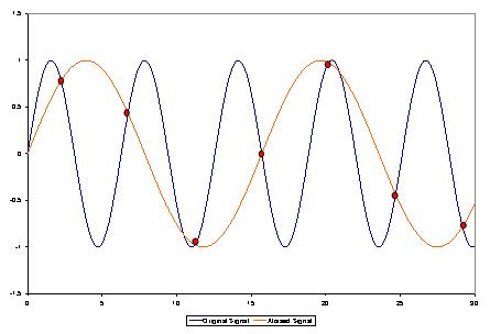
In order to correctly install a data collection in a digital oscilloscope one should follow a simple rule - the sampling rate must be at least 5-10 times higher than the frequency signal, in that case you will not have the issues that we just discussed.
This applies to all digital oscilloscopes and in no way connected to any particular make or model of oscilloscope or its probes.
Up
|
Back to the section
|
|


