|
||||
|
|
|||
|
||||
|
|
|||
|
Search
Log in
|
ACT-1112 Cable Locator
The cable locator is used for general purposes. It is ideal for tracing cables in walls and underground, locating fuses/breakers on final circuits and locating interruptions and short-circuits in cables and electrical floor heating systems. It can be also used for tracing metallic water and heating pipes. The unit is supplied as a complete kit comprising of a transmitter and receiver in a purpose-made carry case. The receiver also incorporates a torch function for working in dimly lit locations.
Technical Specifications
Environmental Specifications
Safety Specifications
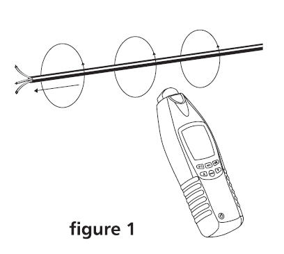
Size(H×W×D): 7,5in × 2,4in × 1,5in/ 190mm × 60mm × 37mm Weight: 8,1oz / 229 g Operating Principle and use of cable locators
The Cable Locator consists of a transmitter and a receiver which is a portable measurement instrument and can be used to detect or trace conductors. The signal generated by the transmitter is made of a modulated current generating an electro-magnetic field around a conductor. This electro-magnetic field induces a voltage within the receiving coil. The induced voltage is amplified, decoded and converted to the original signal by the receiver and finally displayed on the screen. The connecting parameter for the transmitter during an application must be a closed current circuit.
1. General purposes and features:
2. One pole application (In open circuits)Line interruptions in walls and floors. Finding and tracing of lines, sockets, junction box, switches, etc. for house installations. Finding bottlenecks, kinking and buckling and obstructions in installation pipes by means of a metal coil. The ground connector must be connected to a suitable earth. A typical example would be an earthed socket. The tracing depth amounts to 0 ... 2 meters
Note: The tracing depth depends on the medium and application. 3. Double pole application (In complete circuits)When detecting short-circuits or during wire sorting, i.e circuits with or without voltage. Voltage-free circuits are directly supplied by the instrument battery. Example for a complete circuit: Complete circuits are appropriate for: i.e. detecting sockets, switches, etc in live installations.
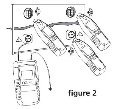
Note: The tracing depth amounts to 0 ... 0.5 meters. The tracing depth depends of medium and application. When connecting in live circuits, safety regulations must be followed. The switching with button 4 from LEVEL I to LEVEL III the sensitivity of Distance is increased up to factor 5. 4. Locating and tracing of lines, lateral circuit branches, sockets, switches and junctions in house installations circuits (one-pole application).When locating and tracing of lines, sockets, switches and junctions in house installations circuits, the circuits must be dead; Neutral line and ground must be connected and fully operational; Connect transmitter to phase and neutral according to figure 4; and Carry out this example as described in the application example.
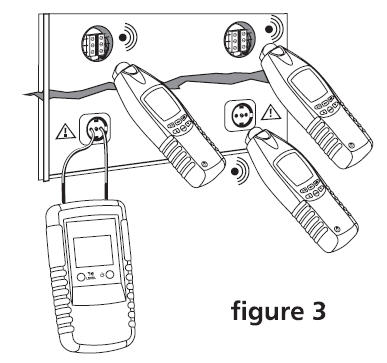
Note: If the supply cable fed with the signal via the transmitter is located, e.g. directly in parallel to other conductors (e.g. cable duct), or if these conductors are crossed, the signal is also input into the other conductors. The fuse must be removed during this example. The switching with button 4 from "LEVEL I" to "LEVEL III" the sensitivity of Distance is increased up to a factor of 5. Setup: manual mode, minimal sensitivity. Tracing depth max 2 meters 5. Locating of line interruptions in the plastic-sheathed cable (one-pole application).When locating of line interruptions, the circuit must be dead; all lines which are not required must be connected to the auxiliary ground in accordance with figure 8, Connect transmitter to one lead and to a neutral according to figure 5; and Carry out this example as described in the application example. The ground connected to the transmitter should be earth from an earthed socket or a water pipe which is properly earthed. When tracing line interruptions in multi colors cables, not that all remaining leads in plastic-sheathed cable or conductor must be grounded in accordance with the regulations. This is required to avoid cross coupling of the fed signal (by a capacitive effect to the source terminals). The tracing depth for sheathed cable and conductors are different, as the individual leads in the sheathed cable are twisted around themselves. The transition resistance of a line interruption must be higher than 100 kOHM. The verification of resistance can be carried out by any multimeter. 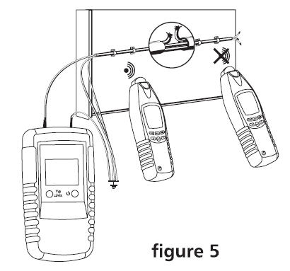
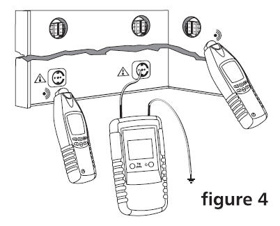
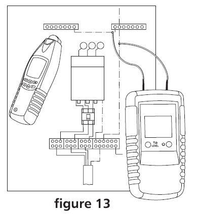
Note: The switching with button 4 from "LEVEL I" to "LEVEL III" the sensitivity of Distance is increased up to factor 5. Tracing depth max 2 meters Setup: manual mode, minimal sensitivity 6. Locating of line interruptions using two transmitters (one-pole application)When locating a line interruption using one transmitter to feed from one conductor end, the location of interruptions may not be precisely located in case of bad conditions due to a field disturbance. The drawbacks described above can easily be avoided when using two transmitters (one from each end) for line interruption detection. In this instance, each of the transmitters are set to a different line code (e.g. transmitter one to code "1 '', the other transmitter to code "2"). A second transmitter with a different line code is not included within the scope of supply and, therefore, has to be ordered separately. If the transmitters are connected in accordance with the figure 12, the receiver indicates "3" at the left side of the line interruption. If you continue further than the interruption, towards the right, the receiver displays "7". If you are directly above the interruption, no line code is displayed, due to the overlapping of both transmitter signals. The line interruption is located exactly in the middle between the displayed line codes "3" and "7". Requirements:
The ground connected to the transmitter and to the wires not being used can be as follows is: an auxiliary ground, an orderly connected ground contact of a home office socket, or an orderly a grounded water pipe. Please make sure during line interruption locating in multi-wire shielded conductors and cables, that all remaining wires are orderly grounded. This is required to avoid inductive disturbance (by capacity coupling). The locating depth for shielded conductors and cables varies, as the individual wires within the shield are twisted. The transition resistance of a line interruption must be higher than 100 kOHM. The verification of resistance can be carried out by any multimeter. 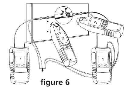
Note: The switching with button 4 from "LEVELl" to "LEVEL III" the sensitivity of Distance is increased up to factor 5. Setup: manual mode, minimal sensitivity. Tracing depth max.2 meters. 7. Error detection for an electrical floor heating (one-pole application)The connection conditions:
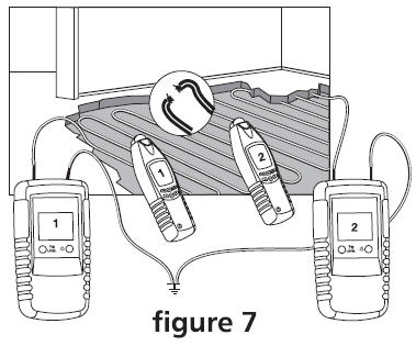
8. Locating of bottlenecks (obstructions) in installation pipes (single-pole application)When locating of bottlenecks in installation pipes, Any circuits in the pipe must be dead and grounded; Connect transmitter to the metal coil and auxiliary ground according to figure 8; and Carry out this example as described in the application example. 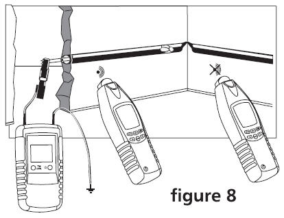
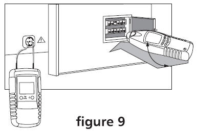
Note: If you have only coiled actual of non conducting material (ex. fiber). We recommend you to slide a copper wire ex. 1.5 mm² up to the x-pipes. The switching with button 4 from "LEVEL I" to "LEVEL III" the sensitivity of Distance is increased up to a factor of 5. Setup: manual mode, minimal sensitivity. Tracing depth max 2 meters. 9. Locating Fuses (dual-pole application)When connecting in live circuits, the safety directions must absolutely be respected./ Insert into the current circuit of a multifamily residential structure within a socket between L 1 and N and switch the transmitter to "LEVEL I"./ You may assign the signal in the secondary distribution and main distribution by transmitter pre-setting "LEVEL I". Thus, fuses and automatic devices can definitely be assigned to a certain current circuit. The detection or assignment of the fuse strongly depends on the wiring realised within the distribution. To obtain a result as precise as possible, the cover should be removed and the supply line to the fuse should be traced./
Note: Set transmitter to LEVEL I. The switching with button 4 from "LEVEL I" to "LEVEL III" the sensitivity of Distance is increased up to s factor of 5. Setup: selective mode, minimal sensitivity. Safety cut-outs of different manufacturers have different installation positions for magnetic coils. If no evident signal can be found by the receiver in the position shown below it is advised to modify the position by 90° towards the left or the right. 10. Locating of short-circuit in conductors (double-pole application)When locating of short-circuits in conductors, any existing circuits within the cable must be voltage-free; connect transmitter in accordance with Figure 10; and carry out this example as described in the application example. Note that the tracing depth for sheathed cable and conductors are different due to the fact that the individual leads in the sheathed cable are twisted around themselves. Usually, short-circuits can only be correctly detected when the short-circuit resistance is lower than 20 Ohm. The verification of the short-circuit resistance can be carried out with any multimeter. 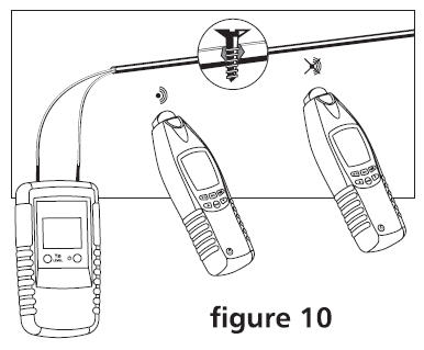
Should the short-circuit resistance amount to more than 20 Ohm, you can try the experiment to detect the error location by means of the line interruption method. You can try with sufficient energy to determine the error location (low ohmic connection) or to burn it in a way ensuring a line interruption. Note: The switching with button 4 from "LEVEL I" to "LEVEL III" the sensitivity of Distance is increased up to a factor of 5. Setup: manual mode, minimal sensitivity. Tracing depth max 0.5 meters. 11. Tracing installed water and heating pipes (one-pole application)The tracing conditions: The line to be located must be separated from the equipotential bonding. For safety reasons the electrical system must not be live! Connect transmitter at foundation ground to the ground socket. The second transmitter socket has to be connected to the conductor to be located. Now the feed line can be traced. The switching with button 4 from "LEVEL I" to "LEVEL III" the sensitivity of Distance is increased up to a factor of 5. 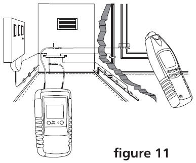
Setup: manual mode, minimal sensitivity. Tracing depth max 2 meters. 12. Detecting the direction of water and heating pipes already installed (one-pole application)When detecting the direction of water and heating pipes already installed, the respective water and heating pipes must be suitably grounded; connect the transmitter according figure 12; and carry out this example as described in the application example. 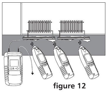
Note: The earth of a properly earthed socket is a suitable ground. The switching with button 4 from "LEVEL I" to "LEVEL III" the sensitvity of Distance is increased up to a factor of 5. Setup: manual mode, minimal sensitivity. Tracing depth max 2.5 meters. 13. Locating a complete house wiring (one-pole application)In order to determine all electrical lines of a house within one working process, proceed as follow:
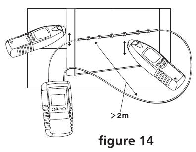
For safety reasons, the system must not be live! Note: The switching with button 4 from "LEVEL I" to "LEVEL III" the sensitivity of Distance is increased up to a factor of 5. Setup: manual mode, minimal sensitivity. Tracing depth max 2 meters 14. Following lines with higher location depth (dual-pole application)If the dual-pole application is carried out on multi-wire cables, the location depth is widely limited. The reason is that the go-and-return lines are installed very closely. Thus, a strong distortion of the magnetic field occurs. The electro-magnetic field may not develop at the bottleneck. This limitation can easily be eliminated when using a separate conductor to simulate the return line. This separate conductor allevel is a larger spreading of the electro-magnetic field. Any conductor or cable reel can be used as separate return conductor. When tracing the conductors, special care has to be taken that the distance between go and return line is larger than the location depth. In practical applications, this amounts to approx 2.0 meters. For this application, humid walls, plaster, etc. have only an insignificant influence on the location depth
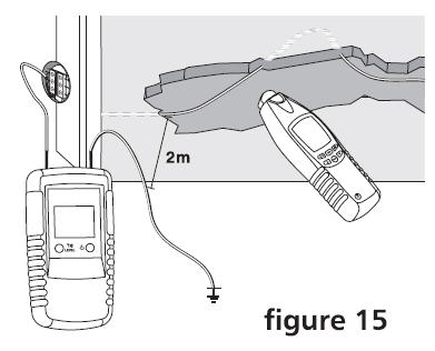
Note: The switching with button 4 from "LEVEL I" to > 2m "LEVEL III" the sensitivity of Distance is increased up to a factor of 5. Setup: manual mode, minimal sensitivity. Tracing depth max 2.5 meters 15. Tracing Conductors within the soil (single-pole application)The connection is realized in compliance with Figure 15
Ensure that the current circuit is not live. Make sure that the distance between the connection to the ground and the conductor to be detected is high. If the distance is too close, no definite assignment of the signal received can be made to one conductor. The tracing depth amounts to maximum 2 meters. Furthermore, the tracing depth strongly depends on the soil characteristics.
The signal intensity level decreases with increasing distance of the fed-in signal (transmitter). Back to the section |