AKTAKOM AMM-3031 is a 11,000 Counts digital multimeter with RLC function
Features
- Digital display counts: 11000
- Safety design
- Data Hold
- Max/Min recording mode
- Auto Ranging
- Auto Power Off: this function can be disabled.
- DMM+RLC
Specifications
DC Voltage (Auto-ranging)
|
Range
|
Resolution
|
Accuracy
|
|
600.0mV
|
0.1mV
|
±0.1% of rdg ± 2digits
|
|
6.000mV
|
1mV
|
|
60.00mV
|
10mV
|
|
600.0V
|
100mV
|
|
1000V
|
1V
|
±0.3% of rdg ± 2digits
|
Input Impedance = 10MΩ
Maximum Input: 1000V DC or 1000V AC RMS = 10MΩ
AC Voltage (Auto-ranging)
|
Range
|
Resolution
|
Accuracy
|
|
6.000mV
|
1mV
|
±0.8% of rdg ± 4digits
|
|
60.00mV
|
10mV
|
|
600.0V
|
100mV
|
|
1000V
|
1V
|
±1.2% of rdg ± 4digits
|
All AC voltage ranges are specified from 5% of range to 100% of range
Input Impedance = 10MΩ
AC Response: 50Hz to 400Hz
Maximum Input: 1000V DC or 1000V AC RMS = 10MΩ
DC Current (Auto-ranging)
|
Range
|
Resolution
|
Accuracy
|
|
600.0uA
|
0.1uA
|
±0.8% of rdg ± 3digits
|
|
6000uA
|
1uA
|
|
60.00mA
|
10uA
|
|
600mA
|
100uA
|
±1.2% of rdg ± 3digits
|
AC Current (Auto-ranging)
|
Range
|
Resolution
|
Accuracy
|
|
600.0uA
|
0.1uA
|
±1.0% of rdg ± 3digits
|
|
6000uA
|
1uA
|
|
60.00mA
|
10uA
|
|
600mA
|
100uA
|
±1.2% of rdg ± 3digits
|
All AC voltage ranges are specified from 5% of range to 100% of range
Overload Protection: FF800mA/1000V and F10A/1000V Fuse.
AC Response: 50Hz to 400Hz
Maximum Input: 6000uA DC on uA range / 800mA DC on mA range / 10A DC on 10A range
Resistance Ω(Auto-ranging)
|
Range
|
Resolution
|
Rx Accuracy
|
|
600.0Ω
|
0.01Ω
|
0.5%±4d
|
|
6.000kΩ
|
0.1Ω
|
0.5%±2d
|
|
60.00kΩ
|
1Ω
|
|
600.0kΩ
|
0.01kΩ
|
|
6.000MΩ
|
0.1kΩ
|
1.5%±8d
|
|
60.00MΩ
|
1kΩ
|
Capacitance (Auto-ranging)
|
Range
|
Resolution
|
Accuracy
|
40.00nF
|
10pF
|
±5.0% of rdg ± 20digits
|
|
400.0nF
|
0.1nF
|
±3.0% of rdg ± 5digits
|
|
4.000uF
|
1nF
|
|
40.00uF
|
10nF
|
|
400.0uF
|
0.1uF
|
|
4000uF
|
1uF
|
±3.0% of rdg ± 10digits
|
Overload Protection: 1000V DC / AC
Inductance (Auto-ranging)
|
Range
|
Resolution
|
Accuracy
|
|
600.0uH
|
0.1uH
|
±7.0% of rdg ± 10digits
|
|
6.000mH
|
1uH
|
±7.0% of rdg ± 5digits
|
|
60.00mH
|
10uH
|
|
600.0mH
|
100uH
|
±8.0% of rdg ± 5digits
|
|
6.000H
|
1mH
|
Overload Protection: 30V DC / AC
Frequency (Auto-ranging)
|
Range
|
Resolution
|
Accuracy
|
9.999Hz
|
0.001Hz
|
±1.2% of rdg ± 3digits
|
99.99Hz
|
0.01Hz
|
999.9Hz
|
0.1Hz
|
9.999kHz
|
1Hz
|
99.99kHz
|
10Hz
|
999.9kHz
|
100Hz
|
9.999MHz
|
1kHz
|
±1.5% of rdg ± 4digits
|
Specifications
- DC Voltage measurement Max Range: 1000V (±0.5%)
- AC Voltage measurement Max Range: 1000V (±0.8%)
- DC Current measurement Max Range: 600mA (±1.2%)
- AC Current measurement Max Range: 600mA (±1.8%)
- Inductance measurement Max Range: 6H (±7.0%)
- Capacitance measurement Max Range: 4mF (±3.0%)
- Frequency measurement Max Range: 9.999MHz (±1.5%)
- Duty Cycle Max Range: 99.9% (±1.2%)
- Temperature measurement Max Range: -20ºC...1000?C / -4?F...1832?F (±3.0%)
- Duty Cycle Max Range: 9.99% (±1.2%)
- Diode Check
- Continuity Test
Safety Conformance
- EN61010-1 CATIV 600V, CATIII 1000V
- Full ranges protection
Size (HxWxD): 7.2x3.2x2.2in/182x82x55mm
Weight: 12.7oz/360g
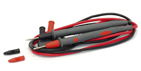
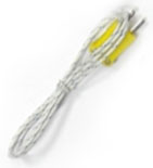
Accessories
1. Test leads
2. 9V battery
3. Thermocouple type K
4. Gift box with carrying case
AC voltage measurements
CAUTION: Do not measure AC voltages if a motor on the circuit is being switched ON or OFF. Large voltage surges may occur that can damage the meter.
- Set the function switch to "AC" position.
- Insert the black test lead banana plug into the negative COM jack. Insert red test lead banana plug into the positive V jack.
- Touch the black test probe tip to the neutral side of the circuit. Touch the red test probe tip to the "hot" side of the circuit.
- Read the voltage in the display

AC/DC current measurements
- Insert the black test lead banana plug into the negative COM jack.
- For current measurements up to 6000μA AC/DC, set the function switch to the μA position and insert the red test lead banana plug into the μA/mA jack, press mode button to select AC or DC.
- For current measurements up to 600mA DC, set the function switch to the mA position and insert the red test lead banana plug into the μA/mA jack, press mode button to select AC or DC.
- Remove power from the circuit under test, then open up the circuit at the point where you wish to measure current.
- Touch the black test probe tip to the negative side of the circuit. Touch the red test probe tip to the positive side of the circuit.
- Apply power to the circuit.
- Read the current in the display.

DC voltage measurements
CAUTION: Do not measure DC voltages if a motor on the circuit is being switched ON or OFF. Large voltage surges may occur that can damage the meter.
- Set the function switch to the "DC" position.
- Insert the black test lead banana plug into the negative COM jack. Insert the red test lead banana plug into the positive V jack.
- Touch the black test probe tip to the negative side of the circuit. Touch the red test probe tip to the positive side of the circuit.
- Read the voltage in the display.

Capacitance measurements
WARNING: To avoid electric shock, disconnect power to the unit under test and discharge all capacitors before taking any capacitance measurements. Remove the batteries and unplug the line cords.
- Set the rotary function switch to the CAP position.
- Insert the black test lead banana plug into the negative COM jack.
- Insert the red test lead banana plug into the positive V jack.
- Touch the test leads to the capacitor to be tested.
Read the capacitance value in the Display
Continuity check
WARNING: To avoid electric shock, never measure continuity on circuits or wires that have voltage on them.
- Set the function switch to the

 position.
- Insert the black lead banana plug into the negative COM jack. Insert the red test lead banana plug into the positive Ω jack.
- Press the MODE button to indicate "" and "Ω" on the display
- Touch the test probe tips to the circuit or wire you wish to check.
- If the resistance is less than approximately 30Ω, the audible signal will sound. If the circuit is open, the display will indicate "OL".
Inductance measurement
WARNING: To avoid electric shock, disconnect both test probes from any source of voltage before making a inductance measurement.
- Select the range switch for the maximum expected inductance.
- Conncet the alligator clips to the inductor leads or insert leads of the inductor into meter’s measuring socket.
- Read the display. The measuring value is direct reading and the electrical unit (mH, H) is indicated.
- When "OL" is displayed, it indicates overrange situation and the rough (higher) range has to be selected.
- If the display indicates one of more reading zeros, shift to the next lower range scale to improve the resolution of the measurement.
When measuring the parameters of components directly on the feed circuit, the circuit needs to be disconnected, and all the inductance discharged until the test leads are connected.
NOTICE: When test small inductance (<600μH), please make sure the test leads short circuit, and press REL button then to test.
WARNING: To avoid electric shock, be sure the inductance has been removed before changing to another measurement function.
Frequency measurement
- Set the function switch to the Hz/Duty position.
- Insert the black test lead banana plug into the negative (-) jack (COM) and the red test lead banana plug into the positive (+) jack (F).
- Touch the test probe tips to the circuit under test.
- Read the frequency in the display. The digital reading will indicate the proper decimal point, symbols (Hz, kHz, MHz) and value.
NOTE: Press the mode key to select the frequency or the duty cycle measuring.
Resistance measurements
WARNING: To avoid electric shock, disconnect power to the unit under test and discharge all capacitors before taking any resistance measurements. Remove the batteries and unplug the line cords.
- Set the function switch to the Ω position.
- Insert the black test lead banana plug into the negative COM jack. Insert the red test lead banana plug into the positive Ω jack.
- Touch the test probe tips across the circuit or part under test. It is best to disconnect one side of the part under test so the rest of the circuit will not interfere with the resistance reading.
- Read the resistance in the display.
Temperature measurements
- Set the function switch to the "Temp" positive and press the MODE key to select the "°C" measuring or "°F" measuring.
- Insert the Temperature Probe into the input jacks, making sure to observe the correct polarity.
- Touch the Temperature Probe head to the part whose temperature you wish to measure. Keep the probe touching the part under test until the reading stabilizes (about 30 seconds).
- Read the temperature in the display.
Note: The temperature probe is fitted with a type K mini connector. A mini connector to banana connector adaptor is supplied for connection to the input banana jacks.
Diode test
- Set the function switch to the position.
- Insert the black test lead banana plug into the negative COM jack and the red test lead banana plug into the positive V jack.
- Press the MODE button to indicate "" and "V" on the display.
- Touch the test probes to the diode under test. Forward voltage will typically indicate 0.400 to 0.700V. Reverse voltage will indicate "OL". Shorted devices will indicate near 0V and an Open device will indicate "OL" in both Polarities.