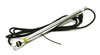
The AKTAKOM ATE-1006 anemometer has a separate telescopic probe, that is easy for operation in different measurement environment.
Features
- 0.5in/13mm dia. heavy duty mini vane with telescope probe available for high temp. air velocity measurement.
- Air flow: CMM (m³/min) and CFM (ft³/min)
- Air velocity: m/s, ft/min, km/h, knots
- Air temperature: °C, °F
- 3 air flow mode: Instant, 2/3 Vmax, Average
- Low-friction ball vane wheels is accurate in both high and low velocities
- Large LCD with dual display
- Record max. and min. reading value
- Data hold
- Thermistor sensor for temp. measurement, fast response time
- RS-232 PC serial interface
Specifications
General specifications:
Circuit: Exclusive one-chip of microcomputer LSI circuit
Display:
- 13mm (0.5") Super large LCD display
- Dual functions display
Measurement:
Air velocity:
- m/s (meters per second)
- km/h (kilometers per hour)
- ft/min (feet/per minute)
- knots (nautical miles per hour)
- mile/h (miles per hour)
Air flow:
- CMM (m3/min)
- CFM (ft3/min)
Air temperature: °C, °F
Data hold
Sensor structure:
- Air velocity & Air flow
- Conventional twisted vane arm and low-friction ball bearing design
- Temperature: Thermistor
Memory recall: Record maximum and minimum reading value with recall
Power off: Auto shut off saves battery life or manual off by push button
Sampling time: Approx. 1s
Operating humidity: Less than 80%RH.
Operating temperature:
- Meter: 0°C to 50°C (32°F to 122°F)
- Probe: 0°C to 80°C (32°F to 176°F)
Data Output: RS-232 PC serial interface
Power Supply: Alkaline or heavy duty type DC 9V battery, 006P, MN1604 (PP3) or equivalent
Power consumption: Approx. DC 8.3mA
Electrical specifications (23±5°C):
Air velocity:
|
Measurement
|
Range
|
Resolution
|
Accuracy
|
|
m/s
|
0.8-12.00
|
0.01
|
±(2%+0.2)
|
|
km/h
|
2.8-43.2
|
0.1
|
±(2%+0.2)
|
|
mile/h
|
1.8-26.8
|
0.1
|
±(2%+0.2)
|
|
ft/min
|
160-2358
|
1
|
±(2%+20)
|
|
knots
|
1.6-23.3
|
0.1
|
±(2%+0.2)
|
Air flow:
|
Measurement
|
Range
|
Resolution
|
Accuracy
|
|
CMM (m3/min)
|
0-999.900
|
0.001-100
|
0.001-9.999
|
|
CFM (ft3/min)
|
0-999.900
|
0.001-100
|
0.001-9.999
|
Air temperature:
Measuring Range: 0°C to 80°C (32°F to 176°F)
Resolution: 0.1°C/0.1°F
Accuracy: 0.8°C/1.5°F (< 60°C)
Weight: 0.84lb/381g, main instrument
Dimensions:
- Main instrument: 7.1x2.8x1.3in/180x72x32mm
- Probe: Vane – 0.5in/13mm dia.; Telescope probe length – Max. 23.6in/60mm
Standard accessories
Measuring procedure
Air velocity measurement
1) Install the "Probe Plug" into the "Probe Input Terminal" (3-14, Fig. 1).
2) Power on the meter by pressing the "Power OFF/ON Button" (3-2, Fig. 1 ).
3) Select VELOCITY measuring mode by pressing "VEL./FLOW Button" (3-7, Fig. 1) to get into velocity measuring mode.
4) Select the desired temperature units, by pressing the "°C/°F Conversion Button" (3-4, Fig. 1).
5) Select the desired air velocity measurement units (mph, ft/min, knot, Km/h, m/s) by pressing the "Unit/T Button" (3-6, Fig. 1 ).
It is ready to measure air velocity when you finish above setting. Regarding other functions relative to Velocity Mode please refer to following description.
6) Data Hold Function:
During the measuring procedure, pressing the "Data Hold Button" (3-3, Fig. 1) will hold the measured value and the LCD will indicate "HOLD" symbol on the left.
* Press the "Data Hold Button" again to release the data hold function.
7) Data Record (Max., Min.)
* Press the "MAX/MIN/. Button" (3-5, Fig. 1) once a while to get into Data Record mode. A "REC" symbol appears on the LCD display. At the same time meter records value received by probe.
* Press again, "Max" symbol appears on the left down corner of the LCD and the Maximum value during recording procedure will displayed on the LCD at the same time.
* Press again, "Min" symbol appears on the left down corner of the LCD and the Minimum value during recording procedure will displayed on the LCD at the same time.
* Press the "MAX/MIN/. Button" for around 3 seconds to exit Data Record mode.
Air flow measurement
1) Install the "Probe Plug" into the "Probe Input Terminal" (3-14, Fig. 1).
2) Power ON the meter by pressing the "Power OFF/ON Button" (3-2, Fig. 1).
3) Select FLOW measuring mode by pressing "VEL./FLOW Button" (3-7, Fig. 1) to get into flow measuring mode.
4) Select the desired air velocity measurement units, (CMM or CFM) by pressing the "Unit/↓ Button" (3-6, Fig. 1).
Note:
Under Air Flow Mode, meter is without Temp, function.
5) Press "SAMPLE AREA Button" (3-13, Fig. 1) to set the measuring area (m2, ft2). The more accurate area setting is the more accurate air flow value measured. When you press the button you may see a "rectangle" symbol appears and the fist digit sparkling. Now you can continue the area setting procedure.
6) Area setting producre uses four buttons "↑", "UNIT/ ↓", "→" and "MAX/MIN/.". (please refer to Fig. 1)
Note:
* " ↑ " button
Press one time to add one of the sparkled digit.
* " UNIT/ ↓ " button
Press one time to decrease one from the sparkled digit.
* " → " button
Press one time to select next digit.
* " MAX/MIN/. " button
Setting the decimal point.
After you set the number you need, please press "ENTER/RESET" button to finish the setting procedure. For instance, if you want to set the sample area 120.3 square feet, please press "UNIT/↓ " button to make sure "ft2" appears on the display. Then press "SAMPLE AREA" button to get into the measuring area setting procedure. Press "↑" button one time to set 1 and press "→" button to select the next digit. Press "↑" button two times to set 2 then press "→" button and press "MAX/MIN/." button to set the decimal point. Press "↑" button three times to set 3 and press "ENTER/RESET" button to finish the sample area setting procedure.
7) Under air flow measuring, we provide 3 kinds of tlow mode for you to apply by pressing the "FLOW MODE" button.
A.2/3V Max mode :
Selecting this mode you can get the 2/3 of the Max. measured value. For instance Max. value is 300 CFM but under 2/3V Max mode you can see 200 CFM only.
B. AVG mode :
Under this mode you can average maximum 20 records by pressing the "AVG.START" button manually. You can see the average number from the right-bottom of LCD. The AVG formula listed as below:
(1st Records + ...+ Nth Records)/N
C. INSTANT mode :
LCD display shows measured number directly.
8) Under "2/3V Max" and "AVG" mode, press "ENTER/RESET" button to reset the previous setting and restart measuring again.
9) Data Hold Function:
During the measuring procedure, pressing the "Data Hold Button" (3-3, Fig. 1) will hold the measured value and the LCD will indicate "HOLD" symbol on the left.
* Press the "Data Hold Button" again to release the data hold function.
10) Data Record (Max., Min.)
* Press the "MAX/MIN/. Button" to get into Data Record mode. A "REC" symbol appears on the LCD display. At the same time meter records value received by probe.
* Press again, "Max" symbol appears on the left down corner of the LCD and the Maximum value during recording procedure will displayed on the LCD at the same time.
Measuring Consideration :
The "IN" mark on the sensor head indicates the mark need to face against the direction of air flow. * Press again, "Min" symbol appears on the left down corner of the LCD and the Minimum value during recording procedure will displayed on the LCD at the same time.
* Press the "MAX/MIN/. Button" for around 3 scconds to exit Data Record mode.
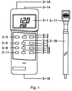
3-1 Display
3-2 Power Off/On Button
3-3 Data Hold Button
3-4 °C/°F conversion Button
3-5 MAX/MIN/. Record Button
3-6 UNIT/↓conversion Button
3-7 VEL./FLOW Button
3-8 → Button
3-9 ↑ Button
3-10 FLOW MODE Button
3-11 AVG.START Button
3-12 ENTER/RESET Button
3-13 SAMPLE AREA Button
3-14 Probe Input Socket
3-15 RS232 Output Terminal
3-16 Battery/Compartment/Cover
3-17 Vane Probe Head
3-18 Vane Probe Handle


