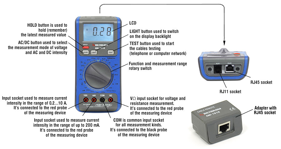
Controls of AM-1016 multimeter
Current measurement
- Connect the black test lead to the COM jack and the red test lead to the A jack for a maximum of 200mA. For a maximum of 10A, move the red lead to the 10A jack.
- Set the rotary switch at desired "A" range position and connects test leads in series with the load under measurement.
- Put down the "AC/DC" when measuring the current. Meter will be transformed between DC and AC range.
- If you need data hold when measuring, you can put on "HOLD", it will hold the reading; if you put the button again, data hold will not continue.
- When only the Figure "1" is displayed, it indicates over range situation and the higher range has to be selected.
Resistance measurement
- Connect the black test lead to the COM jack and the red test lead to the V/Ω jack. (NOTE: The polarity of red lead connection is positive "+")
- Set the rotary switch at desired Ω range position and connect test leads across the resistance under measurement. Read LCD display.
NOTE:
- For resistance above 1MΩ, the meter may take a few seconds to stabilize reading.
- When the input is not connected, i.e. at open circuit, the Figure "1" will be displayed for the overrange condition.
- When checking in – circuit resistance, be sure the circuit under test has all power removed and all capacitors are full discharged.
- At 200MΩ range display is 10 counts when test leads are shorted. These counts have to be subtracted from measuring results. For example, when measuring 100MΩ resistance, the reading will be 101.0 and the correct measuring result should be 101.0-1.0 = 100.0MΩ
Testing battery
- Connect the black test lead to the COM jack and the red test lead to the V/Ω jack.
- Set the rotary switch at the desired "BAT" range position and connect test leads across the battery.
| Position | 1.5V | 6V | 9V |
| Load | 27Ω | 68Ω | 100Ω |
Testing Diode/Continuity
- Connect the black test lead to the COM jack and the red test lead to the V/Ω jack. (NOTE: The polarity of red lead connection is positive "+")
- Set the rotary switch at
 position and connect the red lead to the anode, the black lead to the cathode of the diode under testing. The meter will show the approx. Forward voltage drop of the diode. If the lead connection is reversed, only Figure "1" will be displayed. If continuity exists (i.e., resistance less than about 70Ω), built – in buzzer will sound.
Testing Network Cable (RJ45)
CAUTION! DO NOT use on the circuits as it may damage the tester.
The network tester is suitable for T168A, T568B, 10Base-T and Token Ring.
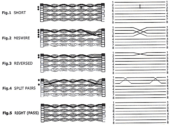
The Network Cable Tester will check a fault condition in the above descending order before detecting other fault conditions. The detection and indication of the presence of a fault is handled on a. "one-pertest" basis. Once a fault is corrected, it is recommended the cable be tested again for other faults.
OPEN There is no "OPEN" indication. A typical cable may have 2, 3, or 4 pairs. OPENS are displayed as an unlit symbol. The user will determine if a pair is present and continuous or OPEN by comparing the illuminated symbol to the expected number of pairs that should be good.
SHO. A short circuit condition exists (see Fig.1).
MIS. Indicates the improper assignment of individual wire pairs to pins for the wiring schemes tested (see Fig.2).
REV. Reverse wiring means the pin for one wire in a pair is connected to the opposite pin for the pair in the remote jack (see Fig.3).
SPL. Split pairs occur when the tip (positive conductor) and ring (negative conductor) of two twisted pairs are interchanged (see Fig.4).
- Connect the RJ45 test jack to one end of the cable to be tested.
- Connect the remote unit to the other end of the cable.
- Push TEST button to perform test. Example: The Cable Fault is a SHORT on Pair 1-2 and Pair 3-6, the LCD status will be as follows: Pair 1-2, Pair 3-6, Pair 4-5, Pair 7-8, SHIE and SHO will display at the same time.
- Push TEST button again, Pair 1-2, Pair 3-6 and SHO will display. Continue to Push TEST button, the next pairs will display.
Testing Telephone Line (RJ11)
- Connect the RJ11 test jack to one end of the telephone line to be tested.
- Connect the UAX (Telephone Unit Automatic Exchange) to the other end of the line.
- Push "TEST”' button to perform test.
Voltage measurement
- Connect the black test lead to the COM jack and the red test lead to the V/Ω jack.
- Set the rotary switch at the desired "V" range position and connect test leads across the source or load under measurement.
- Put down the "AC/DC" when measuring the voltage. Meter will be transformed between DC and AC range.
- If you need data hold when measuring, you can put on "HOLD", it will hold the reading; if you put the button again, data hold will not continue.
- When only the figure "1" is displayed, it indicates over range situation and the higher range has to be selected.


