|
|
AM-1072 Digital Multimeter
AM-1072 Digital Multimeter
|
|
Digital push-button control multimeter, 3 5/6 digit LCD (5999), the basic error of 0.5%. Measurement of DC Voltage of 1000V ± (0.5%+4); AC Voltage of 750V ± (1%+10); DC Current of 10A ± (1.0%+10); AC Current of 10A ± (1.5%+10), Resistance of 60MΩ ± (0.8%+4); Capacitance up to 60mF ± (2.5%+20); Frequency of 100kHz ± (0.5%+8). Continuity test, diode test, scanning, auto power off; protection against overload, misconnection and electric shock, discharge indicator, 2 fuses, backlight. Power: 9 V. Dimensions: 185x93x48mm / 7.3x3.7x1.9in, weight: 330g / 11.6oz.
Manuals:
|
|
AKTAKOM AM-1072 multimeters are designed to measure DC and AC, DC and AC voltage, resistance, capacitance (up to 60 µF!), frequency, diode control and continuity test. High safety and reliability are provided with 2 fuses, protective holster and also the protection against overcurrent and misconnection.
Features
- Display mode: LCD.
- Maximum display: 5999.3 5/6 display automatic polarity display and unit display.
- Measurement mode: dual integration A/D conversion
- Sampling rate: About 3 time/s
- Over rang: Display "OL"
- Low voltage display: the symbol
 displayed. displayed.
- When it is over 30V AC/DC voltage, the symbol
 is displayed is displayed
- Working temperature: 0…40 °C
- Storage temperature: -10…50 °C, relative humidity <80%
- Power: 9V
- Volume (Dimensions): 185x91x49mm / 7.3x3.6x1.9in
- Weight: About 408g / 14.4oz (including battery)
Accessories
1. Test Leads

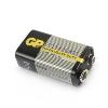
2. 9V battery (design may vary)
3. Operational manual

| AM-1072 Digital Multimeter - front view |
|
|
| AM-1072 Digital Multimeter - accessories |
|
|
AC Current Measurement
- Plug the black test leads into the hole of "COM" and the red pen in the holes of "mA" or "10A". Trigger
 or or  to select automatic identification AC/DC current measurements, and if the current is lower than 10% of the range, the automatic identification is lower than its threshold, measurements cannot be conducted. Please press "SELECT" button to select automatic range AC/DC current measurement. to select automatic identification AC/DC current measurements, and if the current is lower than 10% of the range, the automatic identification is lower than its threshold, measurements cannot be conducted. Please press "SELECT" button to select automatic range AC/DC current measurement.
- In case "OL" is displayed on the display, it indicates the current being tested has exceeded the current range, and please select higher ranges for measurements
Caution:
- At the 10A mode, current bigger than 10A cannot be measured, and at mA mode, the current bigger than 600mA cannot be measured.
- Under automatic identification mode, such buttons as "RANGE", "MAX/MIN", "HOLD" do not play the controlling functions.
- When the test leadsis plugged in the input terminal of the current, it is strictly prohibited to have the test leads connected in parallel on any circuits.
AC Voltage Measurement
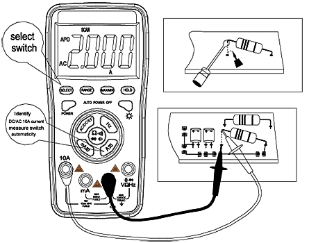
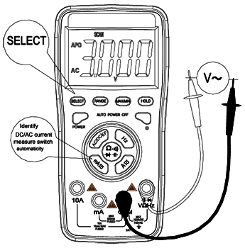
- Trigger "AC/DC/EF", at this time it is at the AC/DC voltage automatic identification mode, and respectively plug in the red and black test leads into the holes of "VΩHz" and "COM", as shown in the following diagram.
- The initial state of the meter is the AC/DC voltage automatic identification mode and a symbol of "SCAN" is displayed; at this time, such buttons as "RANGE", "MAX/MIN", "HOLD" have no controlling functions, and only when "SELECT" button is pressed to select the non-automatic identification mode of the automatic range can such bottoms as "RANGE", "MAX/MIN", "HOLD" play their function controlling.
- Touch the measuring point with the meter measuring pen and connect it in parallel to the circuit being tested, and the polarity of the red test leads wire and the tested voltage value are spontaneously displayed on the display.
Caution:
- Voltages over 1000VDC or 750VAC cannot be tested. The manual range mode is as shown in the LCD. "OL", In case "OL" is displayed for manual range mode, it indicated the range has been exceeded and it is necessary to select higher range mode to complete this measurement.
- At automatic identification and measurement, the AC threshold voltage is 0.5V; in case the voltage to be measured is smaller than 0.5V; trigger the "SELECT" button to select automatic ACV measurement. In case the AC mV mode is used, please select the "RANGE" button.
DC Current Measurement
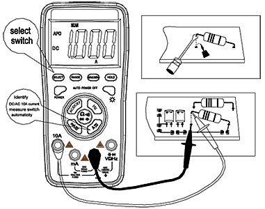
- Plug the black test leads into the hole of "COM" and the red test leads into the hole of "mA" or "10A". Trigger the
 button or button or  button, select automatic identification AC/DC measurement, and at this time such buttons as "RANGE", "MAX/MIN", "HOLD" do not have the controlling functions, and only when the "SELECT" button is pressed in cycle to select automatic range AC or DC current measurement can such buttons as "RANGE", "MAX/MIN", "HOLD" play the relevant function controlling. button, select automatic identification AC/DC measurement, and at this time such buttons as "RANGE", "MAX/MIN", "HOLD" do not have the controlling functions, and only when the "SELECT" button is pressed in cycle to select automatic range AC or DC current measurement can such buttons as "RANGE", "MAX/MIN", "HOLD" play the relevant function controlling.
- In case "OL" is displayed on the display, it indicates the current being measured has exceed the current range, and please select higher ranges for measurements.
Caution:
- At the 10A mode, current bigger than 10A cannot be measured, and at mA mode, the current bigger than 600mA cannot be measured.
- Under automatic identification mode, such buttons as "RANGE", "MAX/MIN", "HOLD" do not play the controlling functions.
- When the test leadsis plugged in the input terminal of the current, it is strictly prohibited to have the test leads connected in parallel on any circuits.
DC Voltage Measurement
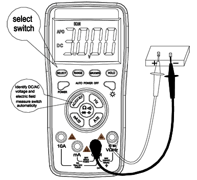
- Trigger "AC/DC/EF", at this time it is at the AC/DC voltage automatic identification mode, and respectively plug in the red and black test leads into the holes of "VΩHz" and "COM", as shown in the following diagram.
- The initial state of the meter is the AC/DC voltage automatic identification mode and a symbol of "SCAN" is displayed; at this time, such buttons as "RANGE, "MAX/MIN", "HOLD" have no controlling functions, and only when "SELECT" button is pressed to select the non-automatic identification mode of the automatic range can such bottoms as "RANGE", "MAX/MIN", "HOLD" play their function controlling.
- Touch the measuring point with the meter measuring pen and connect it in parallel to the circuit being tested, and the polarity of the red test leads wire and the tested voltage value are spontaneously displayed on the display.
Caution:
- Voltages over 1000VDC or 750VAC cannot be tested. When measuring high voltages, special precautions must be taken to avoid e lectrical shock. When measurement is completed, immediately disconnect the test leads and the measured circuit.
- In case "OL" is displayed for manual range mode, it indicated the range has been exceeded and it is necessary to select higher range mode to complete this measurement.
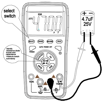
Capacitance Measurement
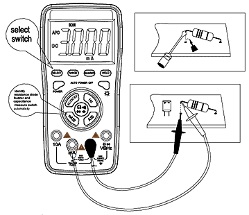
- Press Ω
   button and respectively plug in the red and black test leadss into "VΩHz" and "COM". button and respectively plug in the red and black test leadss into "VΩHz" and "COM".
- After the instrument is turned on, triggering the Ω
   button Is the automatic identification measurement of resistance, diode, buzzer and capacitor. Under the mode of automatic identification, such bottoms as "RANGE", "MAX/MIN", "HOLD" do not play the controlling functions; In case the capacitor being measured is smaller than 0.5nF and bigger than 600μF, please trigger the "SELECT" button, please Trigger the non-automatic identification automatic capacitance measurement mode, and at this time, such buttons as "MAX/MIN", "HOLD", "RANGE" play the functions. )When the mains current is mistakenly fed into the capacitor mode, the circuit may have automatic protection and it will not damage the meter.) button Is the automatic identification measurement of resistance, diode, buzzer and capacitor. Under the mode of automatic identification, such bottoms as "RANGE", "MAX/MIN", "HOLD" do not play the controlling functions; In case the capacitor being measured is smaller than 0.5nF and bigger than 600μF, please trigger the "SELECT" button, please Trigger the non-automatic identification automatic capacitance measurement mode, and at this time, such buttons as "MAX/MIN", "HOLD", "RANGE" play the functions. )When the mains current is mistakenly fed into the capacitor mode, the circuit may have automatic protection and it will not damage the meter.)
Caution:
- When measuring the capacity, all the powers within the tested circuits must be disconnected and the capacitance shall be sufficiently discharged; when measuring big capacitors, it takes a longer time.
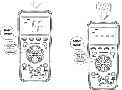
Electric Field Measurement
- After triggering the "AC/DC/EF" button, trigger "SELECT" button in cycle, until the LCD displays "EF", at this time, the meter enters the electric field measurement mode.
- Put the area of the meter near the arrow near the measured object.
- The strength of the electric field is judged by the number of “—” displayed on the LCD display, and based on the interval and continuous beeping sound produced by the buzzer of the EF strength.
Caution:
- It is prohibited to input any voltage at any input ports.
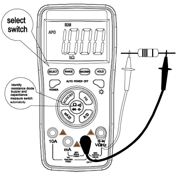
Resistance Measurement
- Trigger Ω
   button, and respectively plug the red and black test leads into the holes of "VΩHz" and "COM" button, and respectively plug the red and black test leads into the holes of "VΩHz" and "COM"
- After the instrument is started, triggering Ω
   button is the automatic identification measurement of resistor, diode, buzzer and capacitor. Under the mode of automatic identification such buttons of "RANGE", "MAX/MIN", "HOLD" do not play the controlling functions, and in case the measurement is bigger than 1MΩ, only when the "SELECT" button is triggered can the automatic range resistance mode can be measured, and at this time "RANGE", "MAX/MIN", "HOLD" play the controlling functions button is the automatic identification measurement of resistor, diode, buzzer and capacitor. Under the mode of automatic identification such buttons of "RANGE", "MAX/MIN", "HOLD" do not play the controlling functions, and in case the measurement is bigger than 1MΩ, only when the "SELECT" button is triggered can the automatic range resistance mode can be measured, and at this time "RANGE", "MAX/MIN", "HOLD" play the controlling functions
Caution:
- When measuring the capacity, all the powers within the tested circuits must be disconnected and the capacitance shall be sufficiently discharged When measuring the resistance, any occurrence of voltage may Lead to inaccurate readings, and if the 250V protection voltage is exceeded, it may damage the meter or threaten the safety of the user.
- When the range of 600Ω is in use, first sort-circuit the test leadss and measure the resistance of the lead wires and then deduct it in the actual measurement.
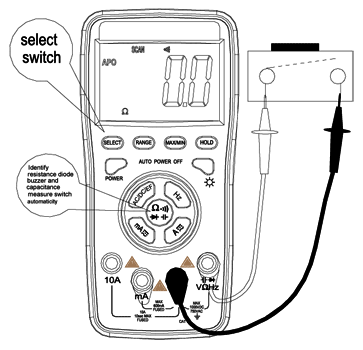
Diode and On-and-Off Test
- Press Ω
   button and respectively plug the red and black pens into "VΩHz" and "COM". button and respectively plug the red and black pens into "VΩHz" and "COM".
- After the instrument is started, triggering Ω
   button is the automatic identification measurement of resistance, diode, buzzer and capacitance. Under the mode of automatic identification such buttons of "RANGE", "MAX/MIN", "HOLD" do not play the controlling functions, trigger "SELECT" to select the diode or buzzer measurement, at this time such buttons as "MAX/MIN". "HOLD" play the controlling functions. button is the automatic identification measurement of resistance, diode, buzzer and capacitance. Under the mode of automatic identification such buttons of "RANGE", "MAX/MIN", "HOLD" do not play the controlling functions, trigger "SELECT" to select the diode or buzzer measurement, at this time such buttons as "MAX/MIN". "HOLD" play the controlling functions.
- Connect the red test leads to the positive of the diode, the black test leads to the negative of the diode.
Caution:
- In case the diode is open circuit or the polarities are connected reversely, "OL" will be displayed on the screen.
- When checking the diode, all the powers within the tested circuits must be disconnected and the capacitance shall be sufficiently discharged.
- When the measurement is completed, immediately disconnect the meter and the measured circuit.
Back to the section
|
|

