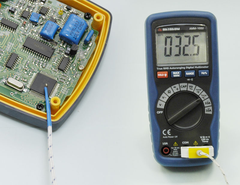
AKTAKOM AMM-1032 are compact multimeters with double molded plastic housing and over sized high contrast 6000 counts LCD display. Theyre all C AT III rated for 600V
Safety Conformance
- EN61010-1 CATIII 600V, CATII 1000V
- Double molded plastic housing
- Full ranges protection
Features
- Digital display counts: 6000
- True RMS measurements
- Analog bargraph/segments: 61-segments
- Safety design
- Data Hold
- MAX/MIN recording mode
- Auto Ranging
- Adaptor ACA function
- Non-Contact ACV detection
Specifications
|
Function
|
Range
|
Resolution
|
Accuracy
|
|
DC Voltage
|
600mV
|
0.1mV
|
±(0.5%reading+2digits)
|
|
6V
|
0.001V
|
±(1,2%reading+2digits)
|
|
60V
|
0.01V
|
|
600V
|
0.1V
|
|
1000V
|
1V
|
±(1.5%reading+2digits)
|
|
AC Voltage (50/60Hz, TRMS)
|
6V
|
1mV
|
±(1,5%reading+10digits)
|
|
60V
|
0.01V
|
±(1,5%reading+10digits)
|
|
600V
|
0.1V
|
|
1000V
|
1V
|
±(2,0%reading+10digits)
|
|
DC Current
|
6A
|
0.001A
|
±(2.5%reading+5digits)
|
|
10A
|
0.01A
|
|
AC Current (50/60Hz, TRMS)
|
6A
|
0.001A
|
±(3,0%reading+5digits)
|
|
10A
|
0.01A
|
|
Resistance
|
600Ω
|
0.1Ω
|
±(1.2%reading+4digits)
|
|
6kΩ
|
1Ω
|
±(1.0%reading+2digits)
|
|
60kΩ
|
10Ω
|
±(1.2%reading+2digits)
|
|
600kΩ
|
100Ω
|
|
6MΩ
|
1kΩ
|
±(2.0%reading+2digits)
|
|
60MΩ
|
10kΩ
|
±(5.0%reading+10digits)
|
Continuity buzzer: <100Ω
|
Capacitance
|
40nF
|
0.01nF
|
±(5.0%reading+50digits)
|
400nF
|
0.1nF
|
±(3.0%reading+5digits)
|
|
4uF
|
0.001uF
|
40uF
|
0.01uF
|
400uF
|
0.1uF
|
±(5.0%reading+5digits)
|
|
4000uF
|
1uF
|
Frequency
|
9.999Hz
|
0.001Hz
|
±(1.5%reading+5digits)
|
99.99Hz
|
0.01Hz
|
999.9Hz
|
0.1Hz
|
±(1.2%reading+3digits)
|
|
9.999kHz
|
0.001kHz
|
99.99kHz
|
0.01kHz
|
999.9kHz
|
0.1kHz
|
|
9.999MHz
|
1kHz
|
±(1.5%reading+4digits)
|
Temperature (thermocouple)
|
-20°C...400°C
|
0.1°C
1°C
|
±(3,0%reading+6digits)
|
|
400°C...760°C
|
|
-4°F...1400°F
|
1°F
|
|
General specifications
Display: 6000 counts, analog bar graph.
Overvoltage category: CATII 1000V / CATIII 600V.
Non-contact Voltage Detector: Led/Vibrating
Insulation: Class2, Double insulation.
Polarity: Automatic, (-) negative polarity indication.
Auto Power Off: this function can't be disabled
Overrange: OL mark indication.
Low battery indication: The BAT is displayed when the battery voltage drops below the operating level.
Measurement rate: 2 times per second, nominal.
Operating environment: 0ºC to 50?C (32?F to 122?F) at < 70 % relative humidity.
Storage temperature: -20?C to 60?C (-4?F to 140?F) at < 80 % relative humidity.
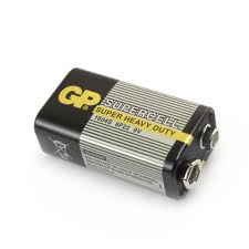
Power: One 9V battery, NEDA 1604, IEC 6F22.
Dimensions (HxWxD): 5.9x2.7x1.9in/150x70x48mm
Weight: Approx.: 255g
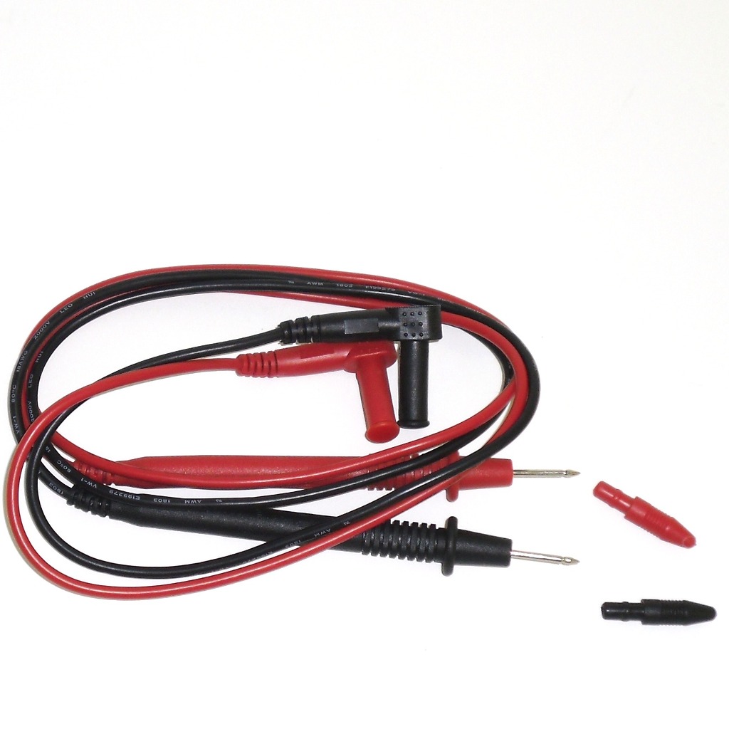
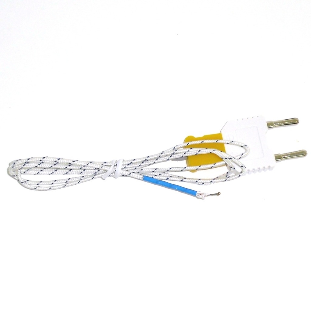
Accessories
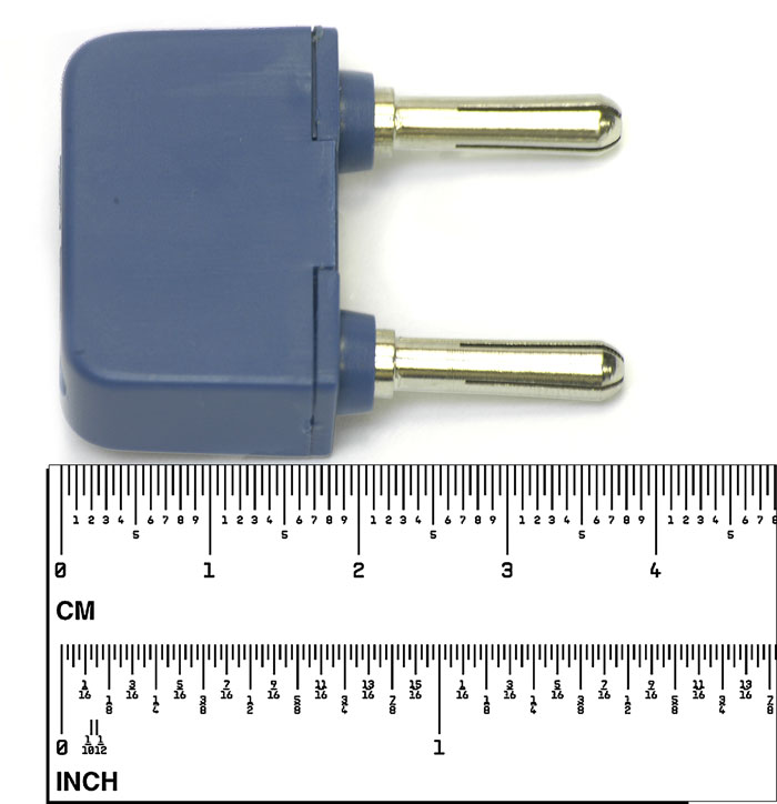
1. Test leads
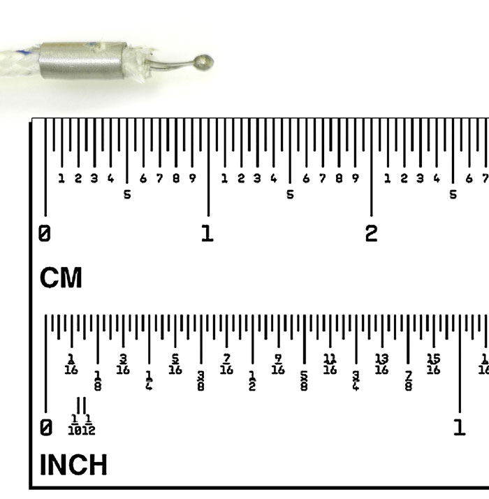
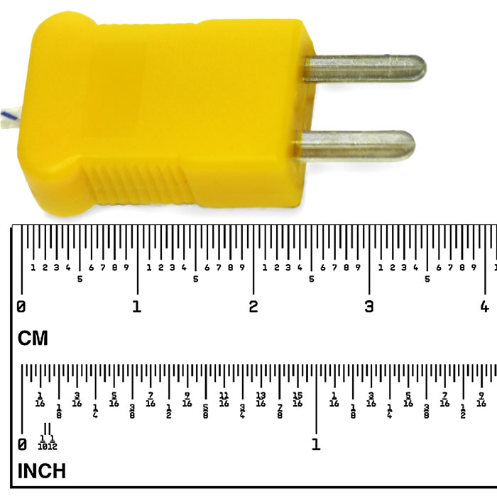
2. Type K temperature probe
3. 9V battery (design may vary)
4. Gift box with carrying case
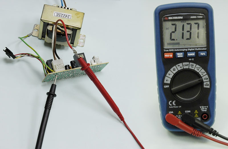
AC current measurement
WARNING: To avoid electric shock, do not measure AC current on any circuit whose voltage exceeds 250V AC.
CAUTION: Do not make current measurements on the 10A scale for longer than 30 seconds. Exceeding 30 seconds may cause damage to the meter and/or the test leads.
- Insert the black test lead banana plug into the negative (COM) jack
- For AC current measurements, set the function switch to the AC 10A position and insert the red test lead banana plug into the 10A jack
- Remove power from the circuit under test, then open up the circuit at the point where you wish to measure current
- Touch the black test probe tip to the negative side of the circuit. And touch the red test probe tip to the positive side of the circuit
- Apply power to the circuit
- Read the current in the display. The display will indicate the proper decimal point, value and symbol.
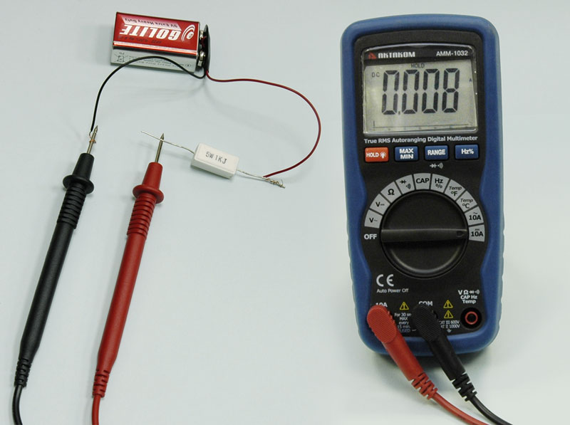
DC current measurement
CAUTION: Do not make current measurements on the 10A scale for longer than 30 seconds. Exceeding 30 seconds may cause damage to the meter and/or the test leads.
- Insert the black test lead banana plug into the negative (COM) jack.
- For DC current measurements, set the function switch to the DC 10A position and insert the red test lead banana plug into the 10A jack.
- Remove power from the circuit under test, then open up the circuit at the point where you wish to measure current.
- Touch the black test probe tip to the negative side of the circuit. Touch the red test probe tip to the positive side of the circuit.
- Apply power to the circuit.
- Read the current in the display. The display will indicate the proper decimal point, value and symbol.
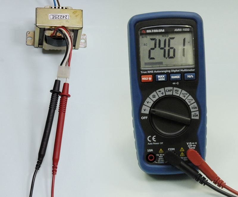
AC voltage measurement
WARNING: Risk of Electrocution. The probe tips may not be long enough to contact the live parts inside some 240V outlets for appliances because the contacts are recessed deep in the outlets. As a result, the reading may show 0 Volts when the outlet actually has voltage on it. Make sure the probe tips are touching the metal contacts inside the outlet before assuming that no voltage is present.
CAUTION: Do not measure AC voltages if a motor on the circuit is being switched ON or OFF. Large voltage surges may occur that can damage the meter.
- Set the function switch to the V AC position.
- Insert the black test lead banana plug into the negative (COM) jack and the red test lead banana plug into the positive (V) jack.
- Touch the test probe tips to the circuit under test.
- Read the voltage in the display. The display will indicate the proper decimal point, value and symbol (AC, V, etc.).
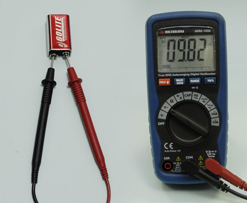
DC voltage measurement
CAUTION: Do not measure DC voltages if a motor on the circuit is being switched ON or OFF. Large voltage surges may occur that can damage the meter.
- Set the function switch to the V DC position ("mV" will appear in the display)
- Insert the black test lead banana plug into the negative (COM) jack and the red test lead banana plug into the positive (V) jack
- Be sure to observe the correct polarity (red lead to positive, black lead to negative)
- Read the voltage in the display. The display will indicate the proper decimal point and value. If the polarity is reversed, the display will show (-) minus before the value.
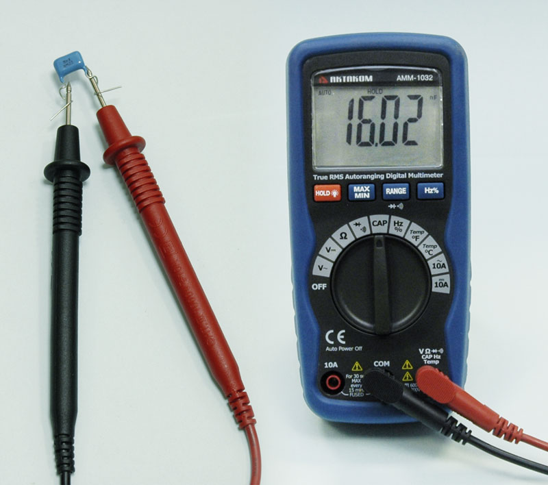
Capacitance measurement
WARNING: To avoid electric shock, disconnect power to the unit under test and discharge all capacitors before taking any capacitance measurements. Remove the batteries and unplug the line cords.
- Set the function switch to the CAP position. (“nF” and a small value will appear in the display).
- Insert the black test lead banana plug into the negative (-) jack (COM) and the red test lead banana plug into the positive (+) jack (CAP).
Touch the test leads to the capacitor to be tested. The display will indicate the proper decimal point, value and symbol.
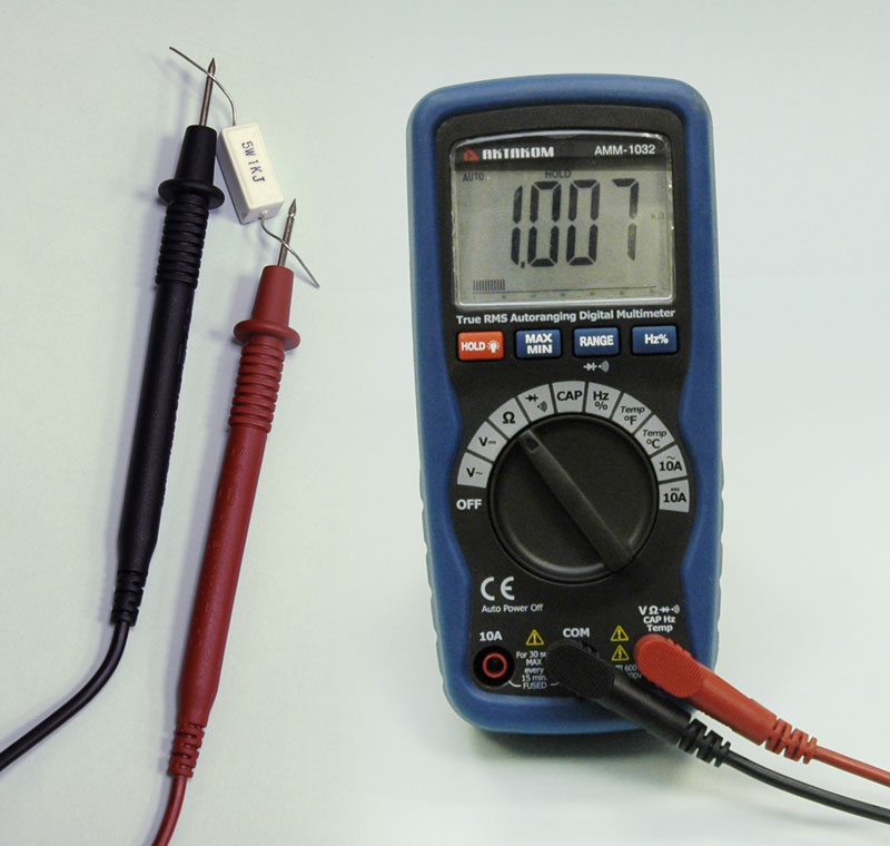
Resistance measurement
WARNING: To avoid electric shock, disconnect power to the unit under test and discharge all capacitors before taking any resistance measurements. Remove the batteries and unplug the line cords.
- Set the function switch to the Ω position
- Insert the black test lead banana plug into the negative (COM) jack and the red test lead banana plug into the positive Ω jack
- Touch the test probe tips across the circuit or part under test. It Is best to disconnect one side of the part under test so the rest of the circuit will not interfere with the resistance reading
- Read the resistance in the display. The display will indicate the proper decimal point, value.
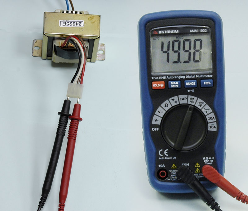
Frequency measurement
- Set the function switch to the FREQ position.
- Insert the black test lead banana plug into the negative (-) jack (COM) and the red test lead banana plug into the positive (+) jack (F).
- Touch the test probe tips to the circuit under test.
- Read the frequency in the display. The digital reading will indicate the proper decimal point, symbols (Hz, kHz) and value.
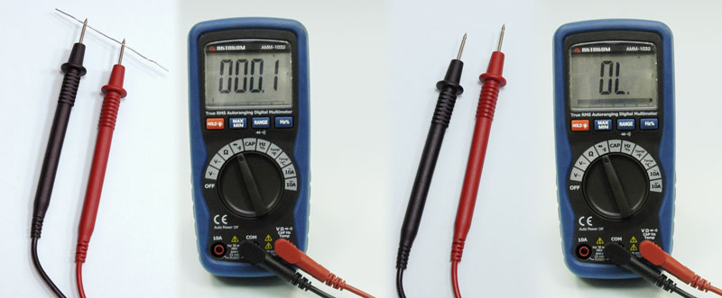
Continuity check
WARNING: To avoid electric shock, never measure continuity on circuits or wires that have voltage on them.
- Set the function switch to the

 position.
- Insert the black lead banana plug into the negative (-) jack (COM) and the red test lead banana plug into the positive (+) jack (Ω).
- Press the button until the symbol appears in the display.
- Touch the test probe tips to the circuit or wire you wish to check.
- If the resistance is less than approximately 100Ω, the audible signal will sound. The display will also show the actual resistance.
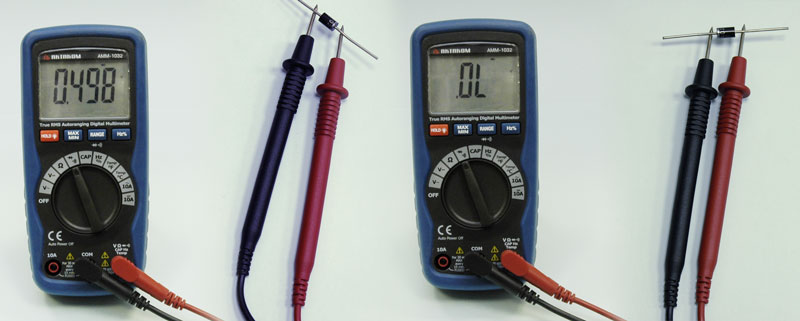
Diode test
WARNING: To avoid electric shock, do not test any diode that has voltage on it.
- Set the function switch to position.
- Press the button until the symbol appears in the display.
- Insert the black test lead banana plug into the negative (-) jack (COM) and the red test lead banana plug into the positive (+) jack (Ω).
- Touch the test probe tips to the diode or semiconductor junction you wish to test. Note the meter reading
- Reverse the probe polarity by switching probe position. Note this reading.
- The diode or junction can be evaluated as follows:
A. If one reading shows a value and the other reading shows OL, the diode is good.
B. If both readings show OL, the device is open.
C. If both readings are very small or 0, the device is shorted.
NOTE: The value indicated in the display during the diode check is the forward voltage.
Temperature measurement
WARNING: To avoid electric shock, disconnect both test probes from any source of voltage before making a temperature measurement.
- If you wish to measure temperature in °F, set the function switch to the °F range. If you wish to measure temperature in °C, set the function switch to the °C range.
- Insert the type K thermocouple probe black test lead banana plug into the negative COM jack and the red test lead banana plug into the positive Temp jack.
- Touch the Temperature Probe head to the part whose temperature you wish to measure. Keep the probe touching the part under test until the reading stabilizes (about 30 seconds).
- Read the temperature in the display. The digital reading will indicate the proper decimal point and value.
WARNING: To avoid electric shock, be sure the thermocouple has been removed before changing to another measurement function.