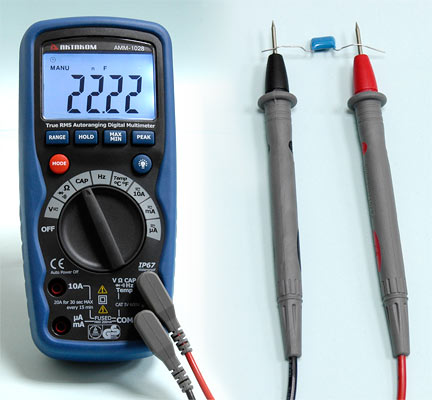
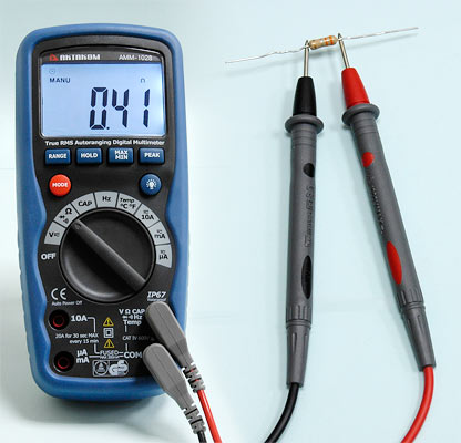
AKTAKOM AMM-1028 multimeter sets the standard with a combination of precise, features, easy-to-use, safety and reliability. It features IP67 dust and waterproof, True RMS, rugged design for heavy duty use. The instrument complies with IEC/EN 61010-1:2001-02 and IEC/EN 61010-031:2002, Class2, double insulation.
Specifications
1. 11000 digital display counts with backlit;
2. True RMS measurement;
3. Relative mode allows you to make measurements relative to a stored reference value;
4. Data hold, MAX/MIN recording mode;
5. Auto ranging;
6. Auto power off: this function can't be disabled
7. Low battery indication;
8. Measurement Rate: 4 times per second, nominal;
9. Wide capacitance range (110mF).
DC Voltage measurement:
Range: 110.00mV, 1.1000V, 11.000V, 110.00V, 1000.0V
Basic accuracy: ±0.09%
Resolution: 0.01mV
AC Voltage measurement:
Range: 110.00mV, 1.1000V, 11.000V, 110.00V, 1000.0V
Basic accuracy: ±0.8%
Resolution: 0.01mV
DC Current measurement:
Range: 110.00μA, 1100.0μA, 11.000mA, 110.00mA, 10.000A
Basic accuracy: ±1.0%
Resolution: 0.01μA
AC Current measurement:
Range: 110.00μA, 1100.0μA, 11.000mA, 110.00mA, 10.000A
Basic accuracy: ±1.5%
Resolution: 0.01μA
Resistance measurement:
Range: 110.00Ω, 1.1000kΩ, 11.000kΩ, 110.00kΩ, 1.1000MΩ, 11.000MΩ, 40.00MΩ
Basic accuracy: ±0.3%
Resolution: 0.01Ω
Capacitance measurement:
Range: 11.000nF, 110.00nF, 1.1000μF, 11.000μF, 110.00μF, 1.1000mF, 11.000mF, 40.00mF
Basic accuracy: ±3.0%
Resolution: 1pF
Frequency measurement:
Range: 1100.0Hz, 11.000kHz, 110.00kHz, 1.1000MHz, 11.000MHz, 110.00MHz,
Basic accuracy: ±0.1%
Resolution: 0.1Hz
Duty Cycle Measurement:
MAX: 99%
Basic accuracy: ±1.2%
Resolution: 0.1%
Diode Check and Continuity Test:
Diode Test: Test current of 1mA maximum, open circuit voltage 3V DC typical
Continuity Check: Audible signal will sound if the resistance is less than 30W (approx.), test current <1.5mA
Temperature Diode Test: Test current of 1mA maximum, open circuit voltage: MAX. 3V typical
NOTE: Accuracy is stated at 65ºF to 83ºF (18ºC to 28ºC) and less than 70% RH.
Size: 7,2in × 3,2in × 2,2in / 182mm × 82mm × 55mm
Weight: 6,4oz / 375g
Accessories
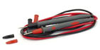
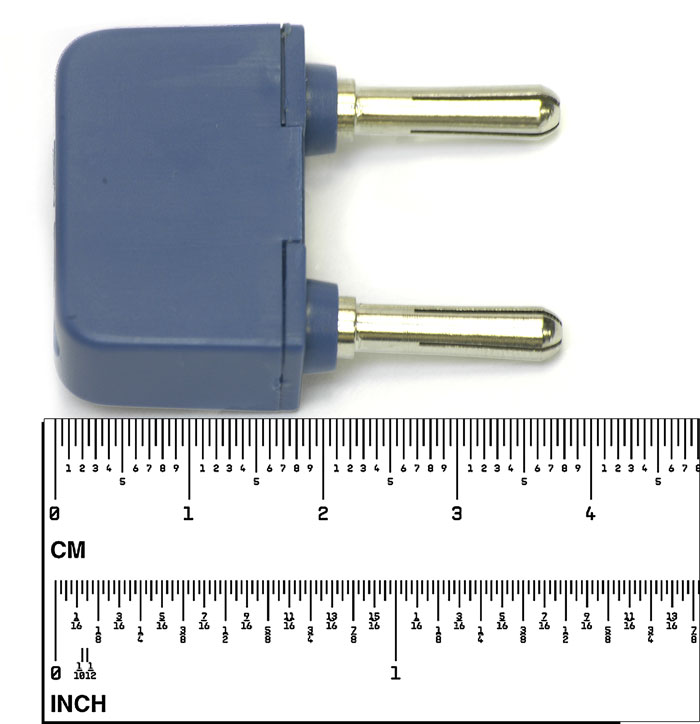
1. Test leads
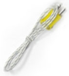
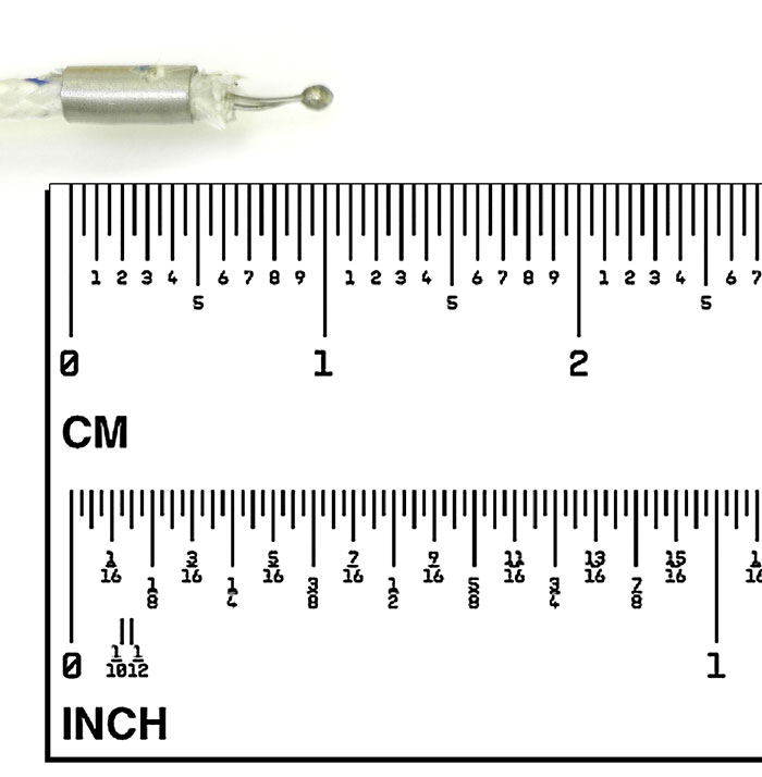
2. Type K temperature probe
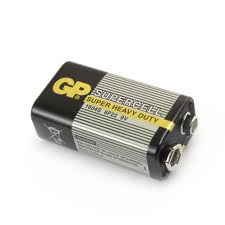
3. 9V battery
4. Gift box with carrying case
AC current measurement
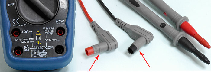
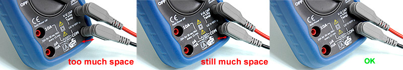
- Insert the black test lead plug into the negative (COM) socket
- For current measurements up to 110uA, set the function switch to the uA position and insert the red test lead plug into the (110uA) jack
- For current measurements up to 110mA, set the function switch to the mA range and insert the red test lead banana plug into the (mA) jack
- For current measurements up to 10A AC, set the function switch to the A position and insert the red test lead banana plug into the 10A jack
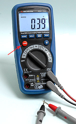
- Press the MODE button. The measurement mode will change between AC or DC as required
- Remove power from the circuit under test, then open up the circuit at the point where you wish to measure current
- Touch the black test probe tip to the negative side of the circuit. And touch the red test probe tip to the positive side of the circuit
- Apply power to the circuit.

DC current measurement
- Insert the black test lead banana plug into the negative (COM) jack
- For current measurements up to 110uA DC, set the function switch to the uA position and insert the red test lead banana plug into the (uA) jack
- For current measurements up to 110mA DC, set the function switch to the mA range and insert the red test lead banana plug into the (mA) jack
- For current measurements up to 10A DC, set the function switch to the A position and insert the red test lead banana plug into the 10A jack
- Press the AC/DC button until “DC” appears in the display
- Remove power from the circuit under test, then open up the circuit at the point where you wish to measure current
- Touch the black test probe tip to the negative side of the circuit. Touch the red test probe tip to the positive side of the circuit
- Apply power to the circuit
- Read the current in the display. The display will indicate the proper decimal point, value and symbol.

DC/AC voltage measurement
- Insert the black test lead into the negative COM terminal and the red test lead into the positive V terminal
- Set the function switch to the VAC or VDC position
- Use the MODE button to select AC or DC Voltage
- Connect the test leads in parallel to the circuit under test
- Read the voltage measurement on the LCD display


Capacitance measurement
WARNING: To avoid electric shock, discharge the capacitor under test before measuring.
- Set the function switch to the CAP capacitance.
- Insert the black test lead banana plug into the negative COM jack and the red test lead banana plug into the CAP positive jack.
- Touch the test probe tips across the part under test.
- Read the capacitance value in the display.
- The display will indicate the proper decimal point and value.
Note: For very large values of capacitance measurement time can be several minutes before the final reading stabilizes. The LCD displays DSC when discharging. Discharging through the chip is quite slow. We recommend the user to discharge the capacitor with some other apparatus.
Frequency measurement
- Set the function switch to the Hz position.
- Insert the black test lead banana plug into the negative (COM) jack and the red test lead banana plug into the positive Hz jack.
- Touch the test probe tips to the circuit under test.
- Read the frequency in the display. The digital reading will indicate the proper decimal point, symbols (kHz, MHz) and value.

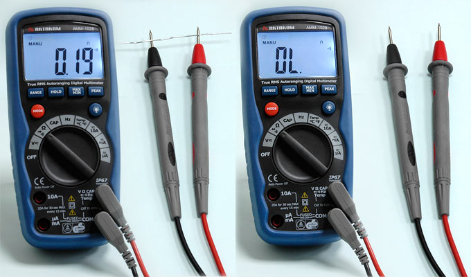
Resistance measurement
WARNING: To avoid electric shock, disconnect power to the unit under test and discharge all capacitors before taking any resistance measurements. Remove the batteries and unplug the line cords.
- Set the function switch to the Ω position
- Insert the black test lead plug into the negative (COM) socket and the red test lead plug into the positive Ω jack
- Press the MODE button until "Ω" appears in the display
- Touch the test probe tips across the circuit or part under test. It is best to disconnect one side of the part under test so the rest of the circuit will not interfere with the resistance reading
- Read the resistance in the display. The display will indicate the proper decimal point, value.
Continuity check
WARNING: To avoid electric shock, never measure continuity on circuits or wires that have voltage on them.
- Set the range switch to the
 position.
- Insert the black lead plug into the COM socket and the red test lead plug into the positive socket.
- Press the MODE button until "" appears in the display.
- Touch the test probe tips to the circuit or wire you wish to check.
- If the resistance is less than 30Ω, the audible signal will sound. The display will also show the actual resistance in ohms.
Diode test
WARNING: To avoid electric shock, do not test any diode that has voltage on it.
- Set the function switch to the
 position.
- Insert the black test lead plug into the COM socket and the red test lead plug into the socket.
- Press the MODE button until "" appears in the display.
- Touch the test probe tips to the diode or semiconductor junction you wish to test. Note the meter reading.
- Reverse the probe polarity by switching probe position. Note this reading.
- The diode or junction can be evaluated as follows:
A. If one reading shows a value and the other reading shows OL, the diode is good.
B. If both readings show OL, the device is open.
C. If both readings are very small or zero, the device is shorted.
NOTE: The value indicated in the display during the diode check is the forward voltage.

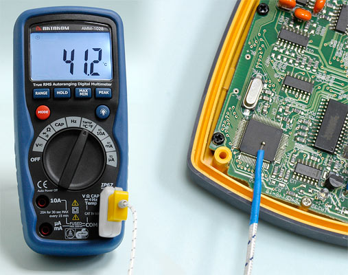
Temperature measurement
- Set the function switch to the ºC position.
- Insert the Temperature Probe into the input jacks, making sure to observe the correct polarity.
- Press the MODE button until “ºF or ºC” appears in the display.
- Touch the Temperature Probe head to the part whose temperature you wish to measure. Keep the probe touching the part under test until the reading stabilizes (about 30 seconds).
- Read the temperature in the display.
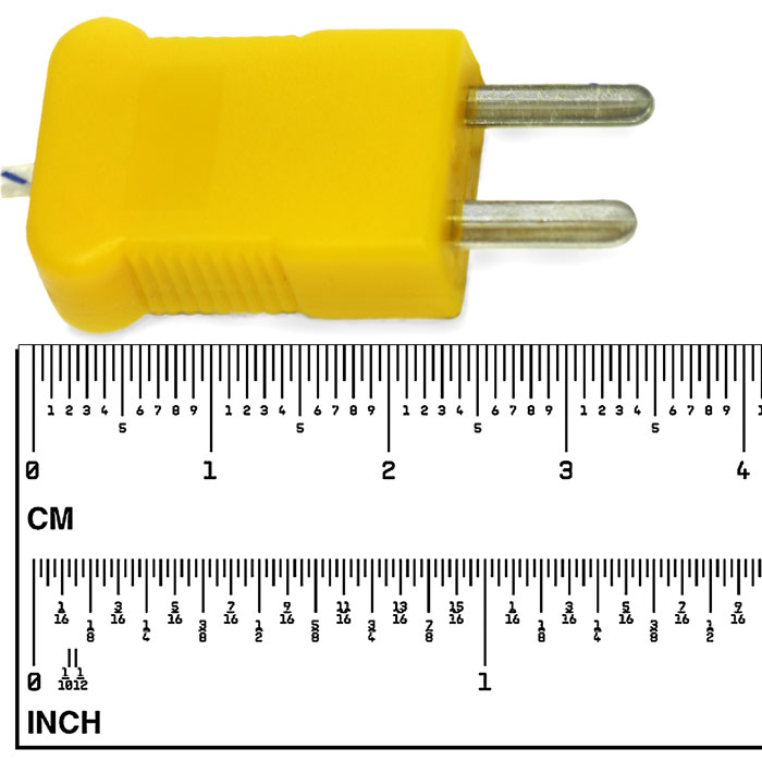
Note: The temperature probe is fitted with a type K mini connector. A mini connector to banana connector adaptoris supplied for connection to the input banana jacks.