AKTAKOM AMM-1009 is a high performance multimeter with double molded plastic housing and over sized high contrast 2000 counts LCD display. It conforms to EN61010-1, Double insulation, CATII 1000V safety standards and full ranges protection.
Features:
1. 2000 digital display counts with backlit
2. Data hold function
3. Auto power off: this function can't be disabled
4. Low battery indication
5. 1000V over-voltage protection
6. Measurement Rate: 2 times per second, nominal
DC Voltage measurement:
Range: 200.0mV, 2.000V, 20.00V, 200.0V, 1000V
Basic accuracy: ±0.5%
Resolution: 0.1mV, 1mV, 10mV, 100mV, 1V
AC Voltage measurement:
Range: 2.000V, 20.00V, 200.0V, 700V
Basic accuracy: ±1.2%
Resolution: 1mV, 10mV, 100mV, 1V
DC Current measurement:
Range: 2.000mA, 200.0mA, 20.00A
Basic accuracy: ±2.5%
Resolution: 1μA, 100μA, 10mA
AC Current measurement:
Range: 2.000mA, 200.0mA, 20.00A
Basic accuracy: ±3.0%
Resolution: 1μA, 100μA, 10mA
Resistance measurement:
Range: 400.0Ω, 4.000kΩ, 40.00kΩ, 400.0kΩ, 4.000MΩ, 40.00MΩ, 400MΩ
Basic accuracy: ±0.8%
Resolution: 0.1Ω, 1Ω, 10Ω, 100Ω, 1kΩ, 10kΩ, 100kΩ
Capacitance measurement:
Range: 4.000nF, 40.00nF, 400.0nF, 4.000μF, 4.0μF
Basic accuracy: ±3.0%
Resolution: 1pF, 10pF, 0.1nF, 1nF, 0.1μF
Frequency measurement:
Range: 4000Hz
Basic accuracy: ±1.5%
Resolution: 1Hz
Temperature measurement:
Max: 760ºC/1400ºF
Basic accuracy:+3%
Resolution:1ºC/1ºF
Diode Check and Continuity Test:
Diode Test: Test current of 1mA maximum, open circuit voltage 2.8V DC typical
Continuity Check: Audible signal will sound if the resistance is less than 50W (approx.), test current <0.3mA
Specifications:
Frequency
Range: 2000Hz
Resolution: 1Hz
Accuracy: +1.5% of rdg + 5 dgts
Sensitivity: 200mV ~ 10V RMS
Overload protection: 250V dc or ac rms.
Sensor: Type K Thermocouple
Overload protection: 250V dc or ac rms.
NOTE: Accuracy is given at 18ºC to 28ºC(65ºF to 83ºF), less than 70 % RH
Size: 7,2 (H) × 3,2 (W) × 2,2 (D) in / 182 (H) × 82 (W) × 55 (D) mm
Weight: 12,7oz /360g
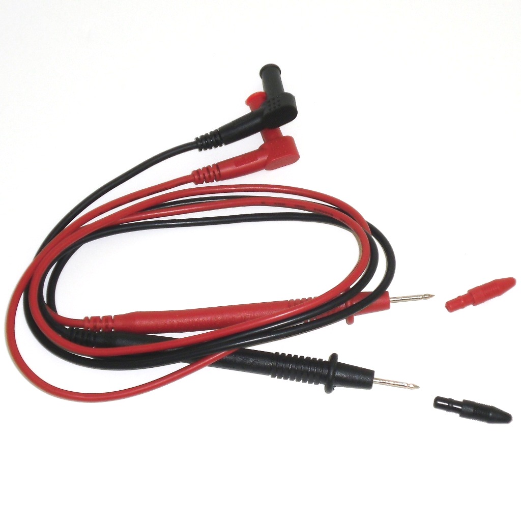
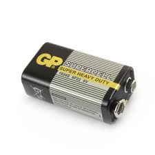
Accessories:
1. Test leads
2. 9V battery (design may vary)
3. Gift box with carrying case

Capacitance measurement
- Set the Function/Range switch to the desired F range.
- Never apply an external voltage to the Cx sockets. Damage to the meter may result.
- Read the capacitance directly from the display.
Current measurement
- Set the Function/Range switch to the desired current type (AC or DC) and range
- For current measurements less than 400mA, connect the red test leads to the mA jack and the black test lead to COM jack
- For current measurements over 400mA or greater, connect the red test leads to the 10A jack and the black test lead to the COM jack
- Remove power from the circuit under test and open the normal circuit path where the measurement is to be taken. Connect the meter in series with the circuit
- Use caution when measuring 10 amps on 10A range for 30s, please waiting for 10 minutes for next measurement of 10 amps for safety reason.
Diode test
- Connect the black test lead to COM jack and the red test lead to VΩ jack.
- Set the function switch to the
 position.
- Turn off power to the circuit under test.
- Touch probes to the diode. A forward-voltage drop is about 0.6V (typical for a silicon diode).
- Reverse the probes. If the diode is good, "OL" is displayed. If the diode is shorted, ".000" or another number is displayed.
- If the diode is open, "OL" is displayed in both directions.
- If the junction is measured in a circuit and a low reading is obtained with both lead connections, the junction may be shunted by a resistance of less than 1kΩ. In this case the diode must be disconnected from the circuit for accurate testing.
Frequency measurement
WARNING: To avoid electric shock, discharge the capacitor under test before measuring.
- Set the Function/Range switch to the "Hz" position.
- Connect the red test lead to the a VΩ jack. and the black test lead to the COM jack.
- Connect the test leads to the point of measur ement and read the frequency from the display.
Logic measurement
- Set the function/range switch to the logic position.
- Connect the red test lead to the VΩ jack and the black test lead to the COM jack.
- Connect the red test lead to the test point and the black lead to the common buss of the logic circuit.
- A "↑" on the display indicates TTL logic high and a "↓" indicates a TTL logic low. Both indicators are on when the point of measurement is toggling high and low.
Resistance and continuity measurement
WARNING: To avoid electric shock, disconnect power to the unit under test and discharge all capacitors before taking any resistance measurements. Remove the batteries and unplug the line cords.
- Set the Function/Range switch to the desired resistance range or continuity position
- Remove power from the equipment under test
- Connect the black test lead to COM jack and the red test lead to VΩ jack.
- Touch the probes to the test points. In ohms, the value indicated in the display is the measured value of resistance. In continuity test, the beeper sounds continuously, if the resistance is less than 100Ω.
- When using 400MΩ Range; The 400MΩ Range has a fixed 20±2-count offset in the reading. When the test leads are shorted together in this range, the meter will display 102.0. The residual reading must be subtracted from the reading obtained in step 4 when this range is used. For example, when measuring 100MΩ on the 400mΩ range, the display will read 102.0, from which the 20 residual is subtracted to obtain the actual resistance of 100.0MΩ.
WARNING: The accuracy of the functions might be slightly affected, when exposed to a radiated electromagnetic field environment, eg, radio, telephone or similar.
Voltage measurement
- Connect the black test lead to COM jack and the red test lead to VΩ jack
- Set the Function/Range switch to the desired voltage type (AC or DC) and range. If magnitude of voltage is not known, set switch to the highest range and reduce until a satisfactory reading is obtained
- Connect the test leads to the device or circuit being measured
- For DC, a (-) sign is displayed for negative polarity; positive polarity is implied


