|
||||
|
|
|||
|
||||
|
|
|||
|
Search
Log in
|
AKTAKOM Power Manager (APM)
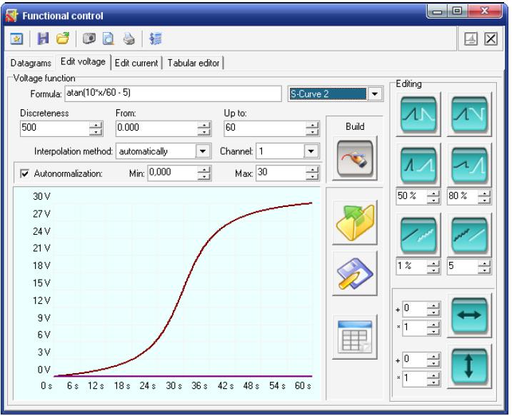
AKTAKOM Power Manager (APM) Software is designed to remotely control AKTAKOM power supplies listed in the compatibility list. APM Software is included in the delivery package of the device models mentioned above or available for an additional payment. Description:APM Software offers wide opportunities for controlling the output voltage and stabilization current both in arbitrary (manual) and in functional modes. Functional control is a powerful APM software tool which allows you not only to automatically control the device via your computer but also to program it for the off-line mode operation in accordance with the predetermined algorithm. Functional control mode in APM software allows you to automatically control the output parameters (voltage or current) of the power supply according to the law set by the graphical and tabular editors. In the convenient graphical editor user may set 10 standard forms of parameter changes (including: sine, square, triangle, saw, flash, pulse, 2 types of exponent, 2 types of S-curves) as well as any arbitrary shape which can be described with a formula. With the help of this software user may control the output voltage and current of power supplies of both types: those equipped with control ADC and without ADC. In case the power supply is with ADC the values are measured hardwarily at the device output. If the power supply is without ADC parameters are specified by the preset value. There is an opportunity to work with the program in compatibility mode of the operation. Features:
To use the program when you connect the device software it requires a key. Without this key the program is capable of operating but has no connection with the device. Without the key you may for example view the previously recorded files. The key can be found on the web site after the device registration with its serial number. The key provides the program operation with one device only.
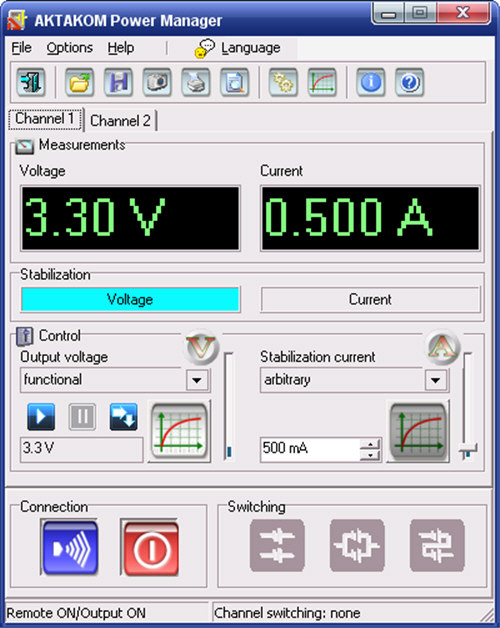
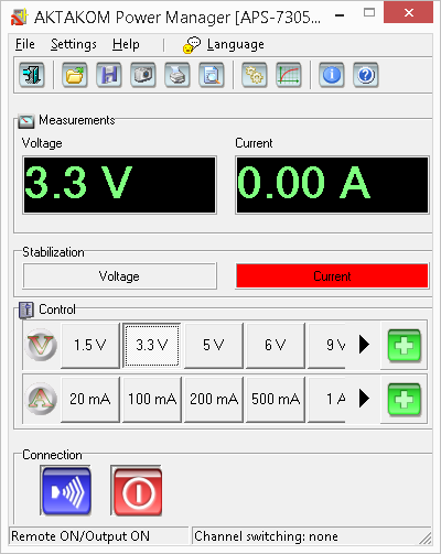
InterfaceProgram user interface consists of operating panels (windows). Every panel contains control elements (CE) which allow the user to influence on the program work as well as on the indicators which reflect all necessary information. In contrast to the CE the user cannot make a direct influence on the indicators. The majority of these elements are the part of Windows standard interface and don't require special use explanation. Control panel at the top of the window is used for quick opening of some program main menu commands. Channels tabs introduce indicators to control the power supply channels. Measurements box contains numerical indicators issued on the following channel of stabilization voltage and current. For the devices equipped with control ADC these values are measured on the device output hardwarily, at the same time the figures are displayed in green. For those devices without ADC the value under measurement is determined by the specified value and all the figures are displayed in red.
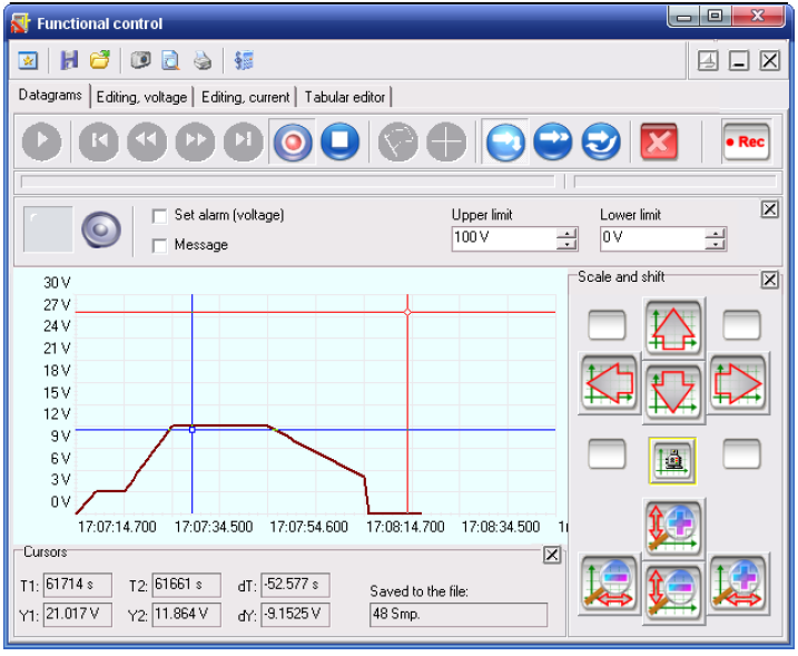
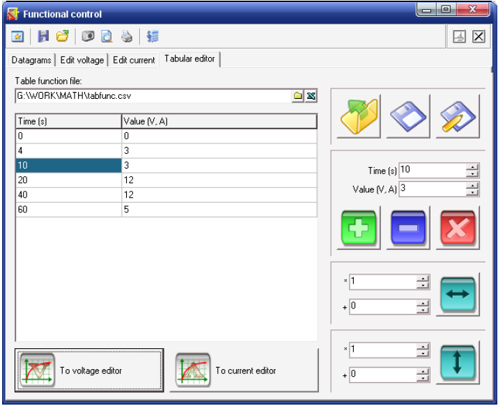
Functional controlThis window shows the specified and measured voltage curves in Diagrams tab and allows automatically controlling the output voltage in accordance with the predetermined law with the help of Graphical editor and Tabular editor.
Under the control panel there are two cursors: the left cursor shows data file reading position, the right one regulates the reading rate. Set alarm - when you set this option the program will control the current voltage to be within the specified limits. If it goes beyond the limits the program will switch on the audible alarm (the indicator will start burning, and the audible alarm will be emitted in case the user hasn't disabled the alarm with
Either the current voltage or the data of the file opened for reading is displayed on the graph in the record mode. In addition to the measured values curve there is a set values curve as well displayed with the same color that is used for the channel measurements curve but the tint is less bright. For those units not equipped with control ADC these curves will be identical. In Cursors box there are measurement values from both graph cursors. Also when saving the data to the file the number of the samples recorded is displayed in this box. Scale and shift allow the user to set the graph scales manually or automatically using Graphical editor
Tabular editor
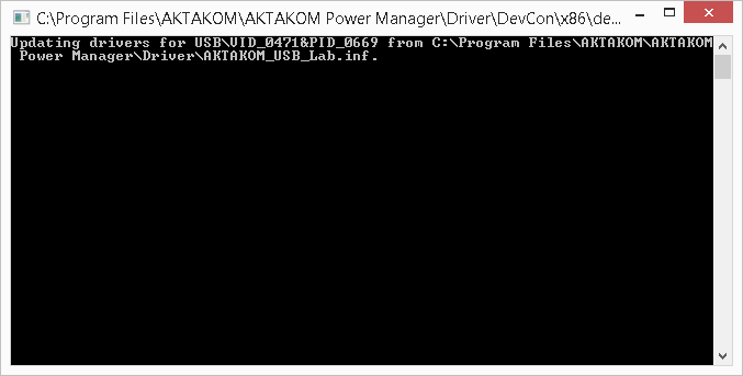
AKTAKOM APS-7303 and 7305 USB driver installation for MS Windows XP, Vista, 7 Software Installation
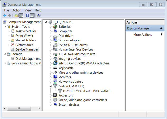
AKTAKOM APS-7313, 7315 and 7612 USB driver installation for MS Windows XP, Vista, 7 Software Installation
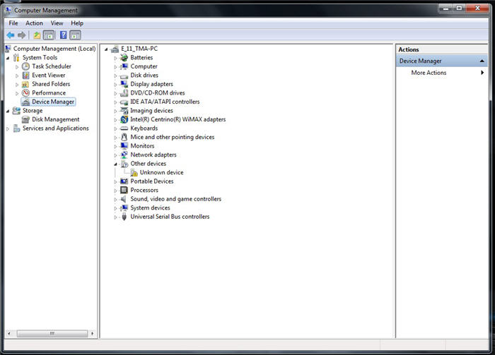
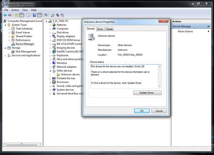
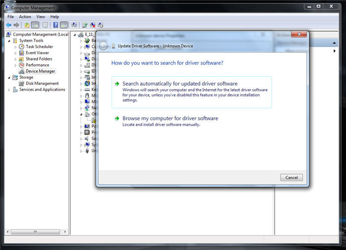
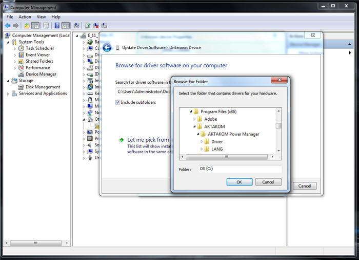
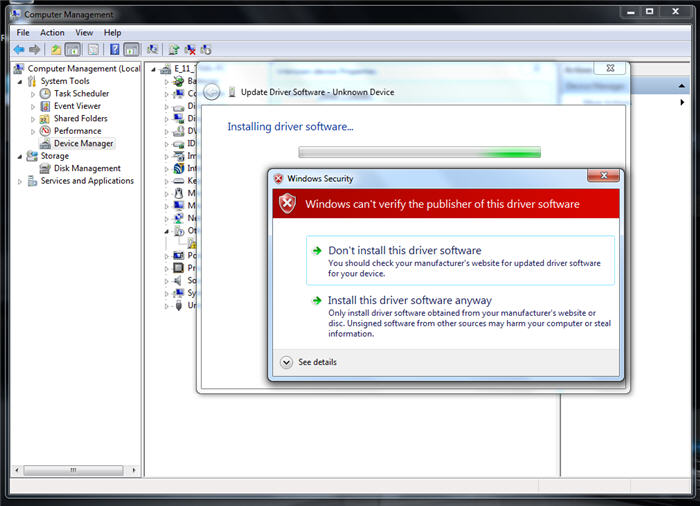
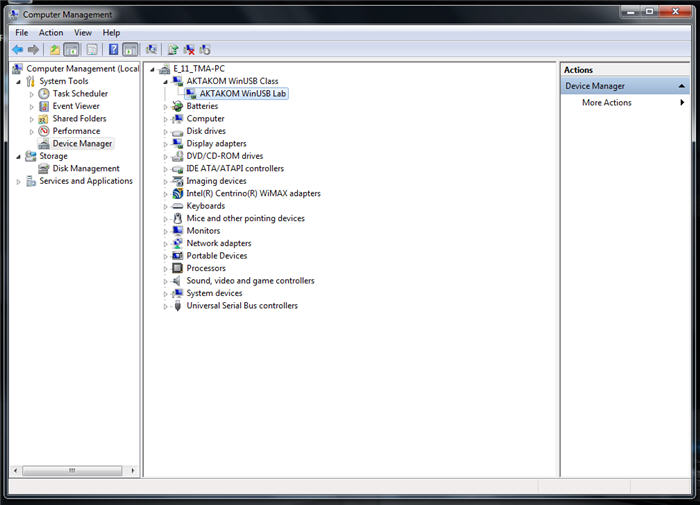
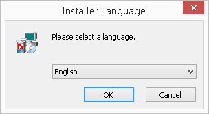
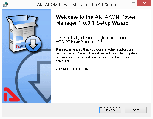
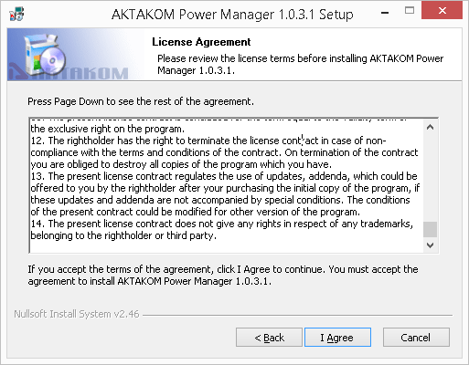
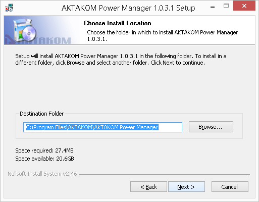
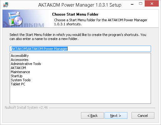
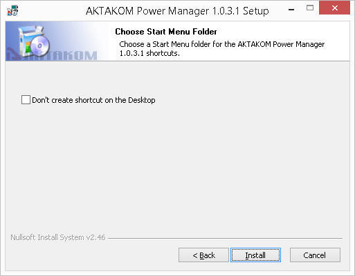
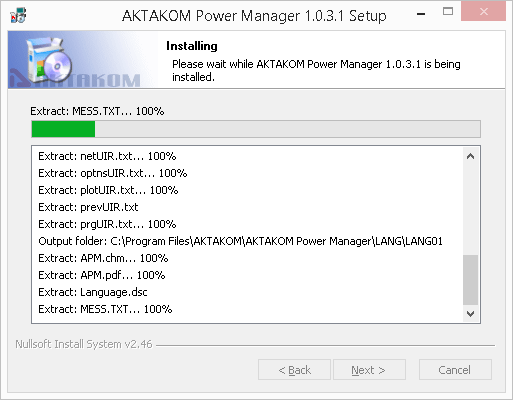
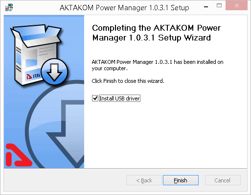
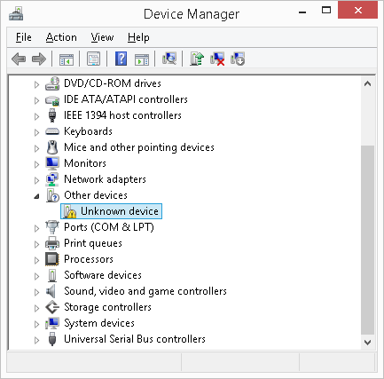
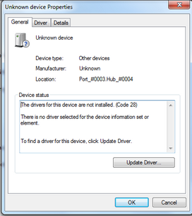
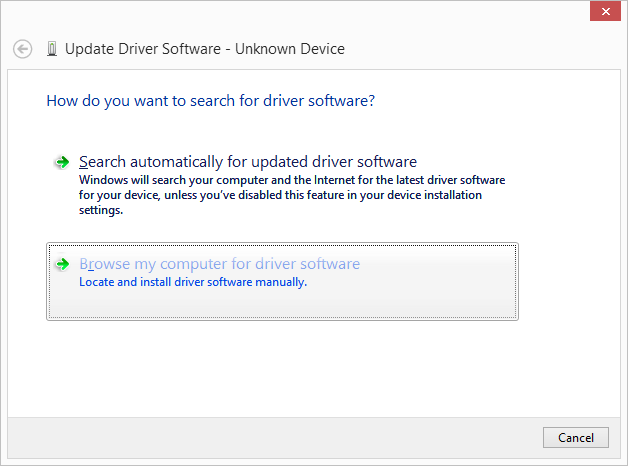
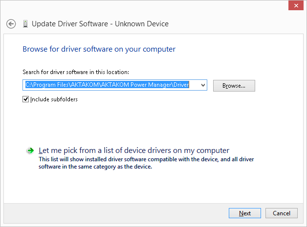
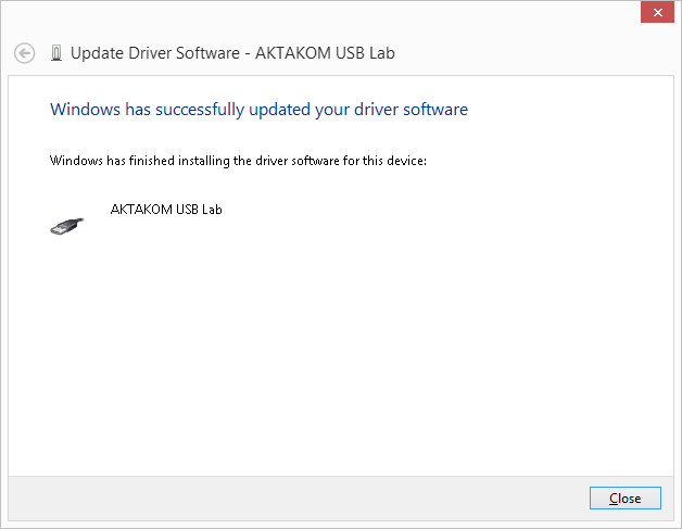
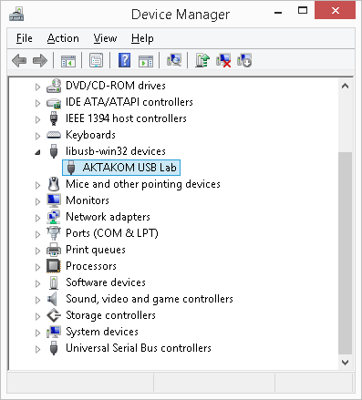
Software Installation InstructionsInsert the software distribution disk into the drive, find “setup.exe” program, run it and then follow the further installation program instruction. When the installation process is finished there will be program group created with the shortcuts for the device program and its Help. You can run them with the help of "Start" menu. Before the device use you should install the USB interface driver. During the software installation all necessary files will be placed into the program working folder, into the Driver subfolder. If you connected the device to the PC during the program installation the driver will be also installed into the system automatically. If, due to some reasons, the driver hasn't been installed you may install it manually at any time later. You may find the description of the driver manual installation procedure in the present Help section below. Do not forget to specify the device type you would prefer to use and its network location if necessary. Therefore you may use the program Options panel. When you start running the program it tries to connect to the device in accordance with the saved settings (see Sockets and Technics tabs description of the Options panel). It's possible to use the program without the device connection. Therefore choose "emulator" as the device type. InstallationAll necessary files are located in the program working directory, C:\Program Files\AKTAKOM\AKTAKOM Power Manager\Driver Driver installation for Windows 7 OS.
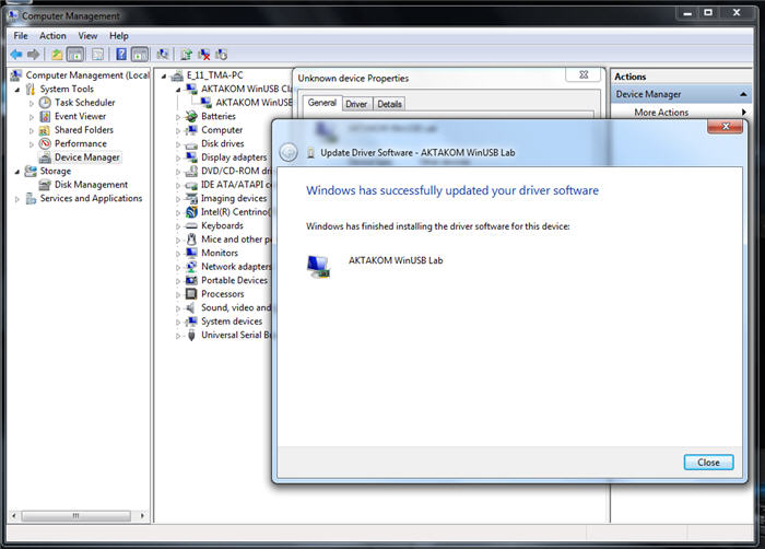
APS-7303 and 7305 device driver installed.
APS-7313, 7315 and 7612 device driver installed.
Standard packageThe software in the standard package of the device has no physical media (CD) and can be downloaded at www.tmatlantic.com after the purchasing and registering the equipment with a serial number. This software is paid-for and its cost is included into device value. In the new version of the software, when connecting the unit for the first time, it will ask for a license (access key). It is available online after product registration. Insert the entire character set by coping and pasting it from www.tmatlantic.com. Follow the instructions on the site. We recommend that you make and keep a copy of the downloaded software. Follow the our websites news releases to receive software updates. Remote control of a power supply with the AKTAKOM Power ManagerControlling the output voltage by using the graphical editorControlling the output voltage by using the table editorDefining the output voltage form by formulaDefining the output voltage form manuallyFrequently Asked Questions
ALL RIGHTS RESERVED. AKTAKOM software is protected under International and Federal Copyright Laws and Treaties. Any unauthorized copy, reprint or use of this material is prohibited. No part of this software may be reproduced or transmitted in any form or by any means, electronic or mechanical, including photocopying, recording, or by any information storage and retrieval system without express written permission from the author / publisher. Windows, Windows logo are either registered trademarks or trademarks of Microsoft Corporation in the United States and/or other countries. Back to the section |

")