|
|
ATE-2001 Thermometer
|
|
Microprocessor circuit assures maximum possible accuracy, provides special functions and features. Heavy duty & compact housing case. Build in temperature linearity & precision cold junction compensation circuit, high accuracy. Fitted with standard type K thermocouple input measuring socket. Multi functions, dual channel temp. input, differential temp. measurement, ℃/℉, 0.1/1 degree. Display: 13 mm(0.5"). Super large LCD display, easy readout. data hold. Dual function meter's display. Wide measuring range from -50 ℃ to 1230 ℃. Memory Recall Records Maximum and minimum readings with recall. Power Off: Auto shut off saves battery life. or manual off by push button. RESOLUTION: 0.1 ℃, 1 ℃,0.1 ℉,1 ℉. ACCURACY: ± ( 1 % + 1 ℃)
Manuals:
|
|
AKTAKOM ATE-2001 is a multi functions thermometer with dual channel temperature input and differential temperature measurement.
Features
- Microprocessor circuit assures maximum possible accuracy, provides special functions and features
- Super large LCD display, easy readout
- Dual function meter's display
- Heavy duty & compact housing case
- Records Maximum and Minimum readings with recall
- Data hold
- Auto shut off saves battery life
- Low battery indicator
- Operates from OO6P DC 9V battery.
- Multi functions, dual channel temp. input, differential temp. measurement, °C/°F, 0.1/1 degree, data hold
- Wide measuring range from -50°C to 1230°C
- Meet any standard type K (NiCr-NiAl) probe
- Fitted with standard type K thermocouple input measuring socket
- Built-in temperature linearity and precision cold junction compensation circuit, high accuracy
Specifications
General specifications:
Circuit: Custom one-chip of micro-processor LSI circuit
Display:
- 13mm (0.5") Super large LCD display
- Dual function meter's display
Sensor Type: Thermocouple K (NiCr-NiAl)
Measurement: Two channel temp. input (T1, T2), differential temperature measurement (T1-T2), °C/°F, 0.11 data hold
Range:
- -50°C to 1230°C
- -50°F to 1999°F
Polarity: Automatic switching, "-" indicates negative polarity
Input Impedance: 10Mohm
Over input indication: Indication of "- - - -"
Memory Recall: Records Maximum and minimum readings with recall
Power Off: Auto shut off saves battery life or manual off by push button
Sampling Time: Approx. 0.8s to 1.0s
Operating Temp.: 0°C to 50°C (32°F to 122°F)
Operating Humidity: Less than 80%R.H.
Power Supply: 006P DC 9V battery (Heavy Duty Type)
Power Current: Approx. DC 6.2mA
Electrical specifications (23±5°C):
|
Temperature range
|
Resolution
|
Accuracy
|
|
°C
|
-200°C to 1370°C
|
0.1°C
|
-199.9°C to 199.9°C
|
±(1%+1°C)
|
|
1°C
|
-200°C to 1370°C
|
|
°F
|
-328°F to 2498°F
|
0.1°F
|
-199.9°F to 199.9°F
|
±(1%+2°F)
|
|
1°F
|
-328°F to 2498°F
|
|
°C
|
T1-T2
|
|
|
±(1%+2°C)
|
|
°F
|
T1-T2
|
|
|
±(1%+3°F)
|
The above accuracy specification applies only to the instrument itself and allowance must be made for limits of error permitted in thermocouple
Dimensions: 7.1x2.8x1.3in/180x72x32mm
Weight: 0.61lb/275g
Standard accessories
- Soft carrying case
- Hard carrying case
Optional accessories
- Instruction manual
- Carrying case
- Temperature probe
| ATE-2001 Thermometer - side view |
|
|
| ATE-2001 Thermometer - rear view |
|
|
| ATE-2001 Thermometer - top view |
|
|
|
Tempetature Measurement
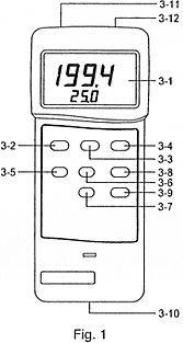
- Push the "Power ON Button" (3-2, Fig. 1) to let the instrument power "ON".
- Determine temperature unit to °C or °F by push the "°C/°F push button" (3-4, Fig. 1). Then the display will show the temperature unit of "°C" or "°F".
- Determine the display resolution to 0.1° or 1° by push "1°/0.1° Button" (3-9, Fig. 1)
- One probe measurement:
Insert one temp, probe plug into the socket T1 (3-11), then push the "Function Button" (3-8, Fig. 1) until the display show the marker "T1" Display will show the temperature reading that measured from the probe.
- Two probe (dual channel) & differential measurement:
- Insert first temp, probe plug into the "T1 Socket" (3-11, Fig. 1).
- Insert second temp, probe plug into the "T2 Socket" (3-12, Fig. 1).
- The main display (upper display) will show the temperature reading of first probe (T1) & the lower display will show the temperature reading of second probe (T2), if push the "Function Button" (3-8, Fig. 1) until the display show the marker "T1".
- The main display (upper display) will show the temperature reading of second probe (T2) & the lower display will show the temperature reading of first probe (T1), if push the "Function Button" (3-8, Fig. 1) until the display show the marker "T2".
- The main display (upper display) will show the differential temperature reading of the first & second probe (T1-T2) & the lower display will show the temperature reading of first probe (T1), if push the "Function Button" (3-8, Fig. 1) until the display show the marker "T1-T2".
 | 3-1 Display
3-2 Power On button
3-3 Data Hold Button
3-4 °C/°F button
3-5 Power Off button
3-6 Memory "Record" Button
3-7 Memory "Call" Button
3-8 Function Button (T1, T2, T1-T2)
3-9 1°/0.1° Button
3-10 Battery Compartment /Cover
3-11 T1 Input Socket
3-12 T2 Input Socket |
Back to the section
|
|


