Digital Multimeter Aktakom AMM-1022 is a portable professional measuring instrument with LCD screen for easy reading. Single operation of a transform switch makes measurement convenient. Overload protection, low battery indication and data hold functions are provided.
Features:
- Max. Display: 1999
- Data Hold
- Diode Test
- Continuity Buzzer
- Transistor hFE test
- Temperature: -20°...1000°C
Specifications:
|
Function
|
Range
|
Resolution
|
Accuracy
|
|
DC Voltage
|
0.2V
|
0.1mV
|
±(0.5%+2)
|
|
2V
|
1mV
|
±(0.5%+3)
|
|
20V
|
0.01V
|
±(0.8%+3)
|
|
200V
|
0.1V
|
±(0.8%+3)
|
|
1000V
|
1V
|
±(0.8%+5)
|
Input impedance: 1MΩ
Max. input voltage: 200mV range: 250VDC or AC rms
2V
1000V ranges: 1000VDC or 750V rms
|
Function
|
Range
|
Resolution
|
Accuracy
|
|
AC Voltage
|
2V
|
1mV
|
-
|
|
20V
|
10mV
|
-
|
|
200V
|
0.01V
|
±(1.2%+5)
|
|
750V
|
1V
|
±(1.2%+5)
|
Input impedance: 1MΩ
Max. input voltage: 200mV range: 250VDC or AC rms
2V
1000V ranges: 1000VDC or 750V rms
Frequency range: 40Hz-400Hz
Response: Average, calibrated in rms of sine wave.
|
Function
|
Range
|
Resolution
|
Accuracy
|
|
DC Current
|
200μA
|
0.1μA
|
±(1%+2)
|
|
2 mA
|
1μA
|
±(1%+2)
|
|
20mA
|
10μA
|
±(1.5%+2)
|
|
200mA
|
100μA
|
±(1.5%+2)
|
|
10A
|
10mA
|
±(3.0%+2)
|
Overload protection: F250mA/250V fuse (10A range unfused).
Max. Input Current: mA Jack: 200mA, 10A Jack: 10A
|
Function
|
Range
|
Resolution
|
Accuracy
|
|
Resistance
|
200Ω
|
0.1Ω
|
±(1%+3)
|
|
2kΩ
|
1Ω
|
±(1%+2)
|
|
20kΩ
|
10Ω
|
±(1%+2)
|
|
200kΩ
|
100Ω
|
±(1%+2)
|
|
2MΩ
|
1kΩ
|
±(1%+2)
|
|
20MΩ
|
10kΩ
|
-
|
Overload protection: 250V DC or 250V AC rms.
|
Function
|
Range
|
Resolution
|
Accuracy
|
|
Temperature
|
-20°C
0°C
|
1°C
|
±(5.0%+4)
|
|
0°C
400°C
|
1°C
|
±(1.0%+3)
|
|
400°C
1000°C
|
1°C
|
±(2.0%+3)
|
Overload Protection: 250V DC or rms AC.
- CATⅢ 600V, CATⅡ1000V
- Maximum value measurement
- Data hold
- Back light
- Display: 2000 counts, digit is 16mm high
- Fuselage colour: Gray
- Weight: Approx. 220g/0.485lb
- Size: 158 x 74 x 31 mm / 6.2 x 2.9 x 1.2 in
Accessories
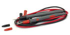
Test Leads
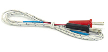
Thermocouple (K type)
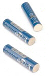
Battery: 1.5V AAA x 3
Instruction Manual

Current measurement
- Set the rotary switch to the desired A= or A∼ range.
- Connect the black test lead to the COM terminal and the red test leads to the mA terminal for a maximum of 200mA. For a maximum of 10A, move the red test lead to the 10A terminal.
- Connect test leads in series with the load in which the current is to be measured.
- Read the displayed value. The polarity of red test lead connection will be indicated when making a DCA measurement.
- When only the figure "1" displayed, it indicates overrange situation and the higher range has to be selected.
 To avoid damage to the meter, use the proper terminals, function, and range for your measurement.
NOTE:
- When only the figure ‘OL’ is displayed, it indicates overrange situation and the higher range has to be selected.
- When the value scale to be measured is unknown beforehand, set the range selector at the highest position.
- “” means the socket of INPUT maximum current is 200mA, over current will destroy the fuse. 10A´s maximum current is 10A, no fuse protection.
Voltage measurement
- Set rotary switch to the desired V= or V∼ range.
- Connect the black and red test leads to the COM and V terminals respectively.
- Connect the test leads to the circuit being measured
- Read the displayed value. The polarity of red test lead connection will be indicated when making a DCV measurement.
- When only the figure "1" is displayed, it indicates overrange situation and the higher range has to be selected.
To avoid electrical shock and/or damage to the instrument, do not attempt to take any voltage measurement that might exceeds 1000VDC or 750VAC rms. Do not apply more than 1000VDC or 750VAC rms between the common terminal and the earth ground.
Resistance measurement
- Connect the black test lead to the COM jack and the red test lead to the Ω jack.
- Set the transform switch at the Ω range position.
- Connect test leads across the resistance under measurement.
- You can get reading from LCD.
To avoid electrical shock and/or damage to the instrument, disconnect circuit power and discharge all high-voltage capacitors before measuring resistance.
NOTE:
- For measuring resistance above 1MΩ, the meter may take a few seconds to stabilize reading. This is normal for high resistance measuring.
- If the resistance being measured exceeds the maximum value of the range selected or the input is not connected, an overrange indication "1" will be displayed.
Temperature measurement
- Set the transform switch at the TEMP range position.
- The LCD display will show the current environment temperature.
- When measuring the temperature with thermocouple, ‘K’ type probe for this meter can be used. Insert the black plug to the COM jack and the red one to the TEMP jack, touch the end of the temperature sensor to the area or surface of the object for measurement.
- You can get reading from LCD.
To avoid electrical shock, do not connect the thermocouples with the electriferous circuit.
Continuity test
- Set the rotary switch to
 range.
- Connect the black and red test leads to the COM and Ω terminals respectively.
- Connect the test leads to the resistance in the circuit being measured.
- When the test lead to the circuit is below 50Ω, a continuous beeping will indicate it.
To avoid electrical shock and/or damage to the instrument, disconnect circuit power and discharge all high-voltage capacitors before testing for Continuity.
Diode test
- Set the rotary switch to
 range.
- Connect the black and red test leads to the COM and Ω terminals respectively.
- Connect the red test lead to the anode, black test lead to the cathode of the diode under testing.
- The meter will show the approx. forward voltage of the diode. If the lead connection is reversed, only figure "1" displayed.
To avoid electrical shock and/or damage to the instrument, disconnect circuit power and discharge all high-voltage capacitors before testing diodes.
Transistor measurement
- Set the rotary switch to hFE range.
- Determine whether the transistor to be tested is NPN or PNP type and locate the Emitter, Base and Collector leads.
- Insert leads of the transistor into proper holes of the hFE socket.
- The meter will show the approx. hFE value at test condition of base current 10μA and VCE 2.8V.
To avoid electrical shock and/or damage to the instrument, before attempting to insert transistors for testing, always be sure that test leads have been disconnected from any measurement circuits.


