|
||||
|
|
|||
|
||||
|
|
|||
|
Search
Log in
|
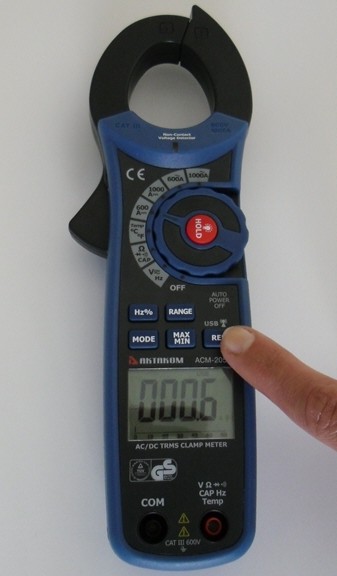
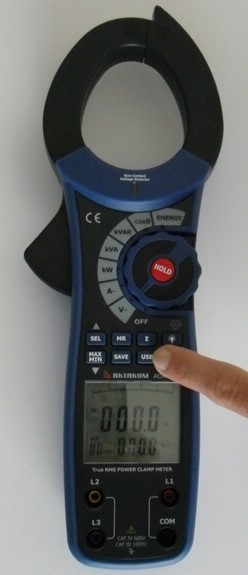
ACM-2353 Clamp Meter
ACM-2353 Professional True RMS 1000A AC Watt Clamp Meter provides accurate Watt, AC Current and Voltage readings regardless of waveforms. Features
Specifications
General Specifications
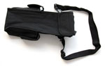
AccessoriesIncluded1. Carrying case
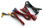
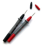
2. Test leads
3. Test probes
4. Crocodile clips
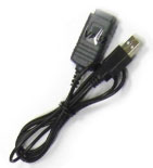
5. USB cable
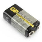
6. 9V battery
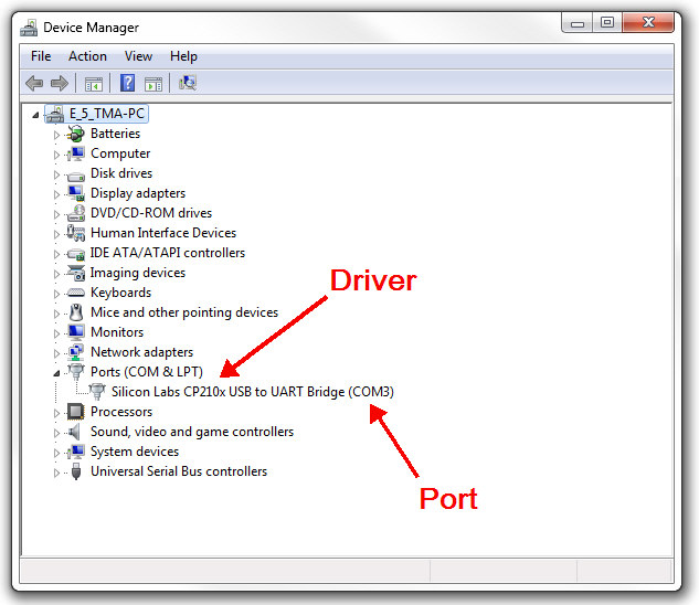
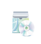
Optional1. Software (Available for download by registration)
AC Current (main display) + AC Voltage (secondary display) Measurement
The AC current ranges are: 40A, 100A, 400A and 1000A. The AC Voltage ranges are: 100V, 400V and 750V To measure AC current + AC voltage, connect the Meter as follows:
Note: When the measurement has been completed, disconnect the connection between the conductor under test and the jaw, and remove the conductor away from the transformer jaw of the Meter.
AC Voltage (main display) + Frequency (secondary display) Measurement
The AC Voltage ranges are: 100V, 400V and 750V. The frequency range is: 50Hz~60Hz. To measure AC voltage + frequency, connect the Meter as follows:
Note: When the measurement has been completed, disconnect the connection between the testing leads and the circuit under test and remove testing leads from the input terminals. Active Energy (main display) + Time (secondary display) MeasurementWarning. To avoid damages to the Meter or harms to you, do you measure higher than AC voltage 750V rms and AC current 1000A rms. To test for Active Energy (main display) + Time (secondary display), connect the Meter as follows:
Note
For more information go to User Manual.
Active Power (main display) + Phase Angle (secondary display) Measurement
Warning. To avoid damages to the Meter or harms to you, do you measure higher than AC voltage 750V and AC current 1000A. To measure active power + phase angle, connect the Meter as follows:
Apparent Power (main display) + Reactive Power (secondary display) Measurement
Warning. To avoid damages to the Meter or harms to you, do you measure higher than AC voltage 750V and AC current 1000A. To measure Apparent Power + Reactive Power, connect the Meter as follows:
Power Factor (main display) + Phase Angle (secondary display) Measurement
Warning. To avoid damages to the Meter or harms to you, do you measure higher than AC voltage 750V and AC current 1000A. To test for Power factor (main display) + Phase angle (secondary display), connect the Meter as follows:
Reactive Power (main display) + Apparent Power (secondary display) Measurement
Warning. To avoid damages to the Meter or harms to you, do you measure higher than AC voltage 750V and AC current 1000A. To measure Reactive Power + Apparent Power, connect the Meter as follows:
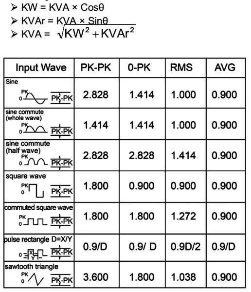
True RMS Measurement and Average Value Measurement
The True RMS measurement method can measure accurately the effective value of non-sine wave input signal. Average value measurement method can measure the mean value of one sine wave input signal, and then displays it as RMS value When the input waveform has distortion, measuring tolerance will be included. The total tolerance depends on the total distortion. Below table shows the waveform coefficient and the relationship and the requested changing factor of sine wave, square wave, pulse rectangle wave, saw tooth triangle wave, RMS value and average value. The clamp Meter software designing base on the following formula:
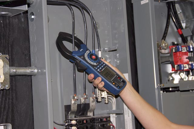
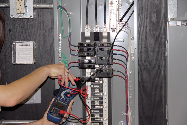
Current measurements with ACM-2353 on branch circuits of an electrical distribution system
Power measurements with ACM-2353 on branch circuits of an electrical distribution system
Frequently Asked Questions
Back to the section |
|||||||||||||||||||||||||||||||||||||||||||||||||||||||||||||||||||||||||||||||||||||||||||||||||||||||||||||||||||||||||||||||||||||||||||||||||||||||||||||||||


 + Frequency (secondary display) Measurement")
 + AC Voltage (secondary display) Measurement")
 + Reactive Power (secondary display) Measurement")
 + Apparent Power (secondary display) Measurement")
 + Phase Angle (secondary display) Measurement")
 + Phase Angle (secondary display) Measurement")
 + Time (secondary display) Measurement")
 + AC Voltage (secondary display) Measurement")


 + Apparent Power (secondary display) Measurement")