|
|
ACM-2103 Clamp Meter
|
|
Measurement range: ACA, DCA, ACV, DCV, Ohms, Diode, Hz, capacitance, duty cycle, continuity beeper. Over-input: Indication of "1" or "-1". Sampling Time: Approx. 0.35 second. Battery: DC 9V battery, heavy duty or Alkaline type, 006P, MN1604 (PP3) or equivalent. Power Consumption: Approx. DC 5mA. Operating Temp.: 0°C to 50°C (32°F to 122°F). Operating humidity: Less than 80% RH. Max. jaw open size: 2.36in/60mm Dia.
Manuals:
|
|
AKTAKOM ACM-2103 is 2 in 1 instrument: 2000 A clamp meter + digital multimeter.
Features
- Meet IEC 1010 CATIII 1000V safety requirement
- True rms reading for ACV & ACA measurement
- 4000 counts, auto range, multi-functions for ACA, DCA, ACV, DCV, Ohms, capacitance, Hz, diode, duty cycle and continuity check
- LSI circuit provides high reliability and durability
- Wide ranges (2000A, 400A) clamp on current measurement both for ACA & DCA
- 4 ranges (400uA, 4000uA, 40mA, 400mA) direct current input measurement both for ACA & DCA
- Overload protection circuit is provided for all ranges
- Data hold, relative key, back light
- Compact & heavy duty ABS and fireproof plastic case
Specifications
General specifications
Display: 15mm (0.6") LCD, 4 digits, Max. indication 5000 (frequency range)
Measurement range: ACA, DCA, ACV, DCV, Ohms, Diode, Hz, capacitance, duty cycle, continuity beeper
Polarity: Automatic Switching, "-" indicates negative polarity
Current Sensor: Hall effect sensor
Zero adjustment:
- DCA: Push bottom adjustment
- Other ranges: Automatic adjustment
Over-input: Indication of "1" or "-1"
Sampling Time: Approx. 0.35 second
Battery: DC 9V battery, heavy duty or Alkaline type, 006P, MN1604 (PP3) or equivalent
Power Consumption: Approx. DC 5mA
Operating Temp.: 0°C to 50°C (32°F to 122°F)
Operating humidity: Less than 80% RH.
Max. jaw open size: 2.36in/60mm Dia.
Electrical specifications (23±5°C)
|
Function
|
Range
|
Resolution
|
Accuracy
|
Overload Protection
|
|
DC/AC voltage
|
400mV (DC only)
|
0.1mV
|
±(0.5%+2d)
|
AC/DC 1000V
|
|
4V
|
0.001V
|
DCV: ±(1%+2d) ACV: ±(1.2%+5d)
|
|
40V
|
0.01V
|
|
400V
|
0.1V
|
|
1000V
|
1V
|
|
DC/AC current (Direct input)
|
400uA
|
0.1uA
|
±(1.2%+5d)
|
AC/DC 500mA (Fuse)
|
|
4000uA
|
1uA
|
|
40mA
|
0.01mA
|
|
400mA
|
0.1mA
|
|
DC/AC current (Clamp on)
|
400A
|
0.1A
|
±(2%+5d)
|
AC/DC 2000A/1000V
|
|
|
2000A
|
1A
|
±(2%+8d)
|
Remarks:
- True rms measurement both for ACV, ACA function.
- Input impedance for ACV & DCV range is 10 Mega ohm
- ACA, ACV frequency response is from 45 to 1KHz
- ACA, ACV specifications are tested on sine wave 50/60 Hz
|
Function
|
Range
|
Resolution
|
Accuracy
|
Overload Protection
|
|
Ohms
|
400 ohm
|
0.1 ohm
|
±(1%+5d)
|
AC/DC 400V
|
|
4 Kohm
|
1 ohm
|
|
40 Kohm
|
10 ohm
|
|
400 Kohm
|
100 ohm
|
|
4 Mohm
|
1 Kohm
|
±(2%+2d)
|
|
40 Mohm
|
10 Kohm
|
±(3.5%+5d)
|
|
Capacitance
|
50nF
|
10pF
|
±(3%+5d)
|
AC/DC 400V
|
|
500nF
|
100pF
|
|
5uF
|
0.001uF
|
|
50uF
|
0.01uF
|
|
Frequency (>5V)
|
5Hz
|
0.001Hz
|
±(1%+5d)
|
AC/DC 1000V
|
|
50Hz
|
0.01Hz
|
|
500Hz
|
0.1Hz
|
|
5KHz
|
1Hz
|
|
50KHz
|
0.01KHz
|
|
100KHz
|
0.1KHz
|
|
Duty cycle
|
1% to 99%
|
0.1%
|
Diode: Short/non conductance, good/defect test
Continuity: If measuring assistance is less than 10 ohm, the beeper will sound
Dimensions: 10x2.9x1.5in/255x73x38mm
Weight: 0.85lb/380g (including battery)
Accessories
Standard accessories
Optional accessories
- Carrying case
- EMF Adapter
- Light Adapter
- Anemometer Adapter
- Pressure Adapter
- Sound Adapter
- Tachometer Adapter
- High Voltage Probe
| ACM-2103 Clamp Meter - rear view |
|
|
| ACM-2103 Clamp Meter - side view |
|
|
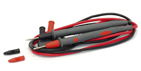
| ACM-2103 Clamp Meter - test leads |
|
|
|
| ACM-2103 Clamp Meter - inputs |
|
|
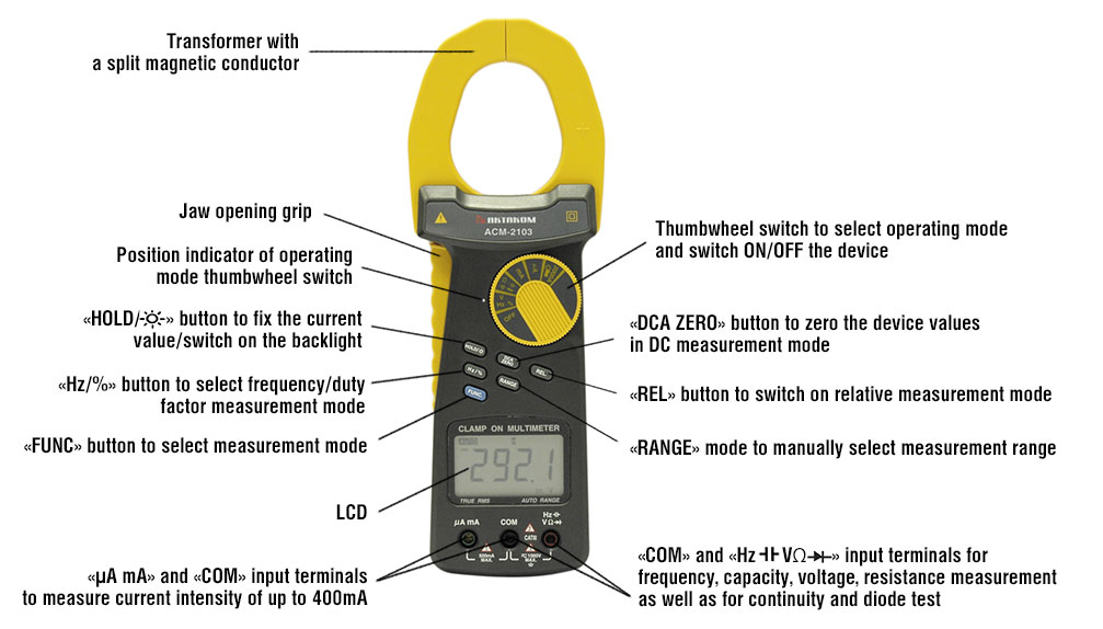
| ACM-2103 Clamp Meter - control buttons |
|
|
| ACM-2103 Clamp Meter - DCV Measurement |
|
|
|
| ACM-2103 Clamp Meter - ACV Measurement |
|
|
| ACM-2103 Clamp Meter - DCA Measurement |
|
|
| ACM-2103 Clamp Meter - ACA Measurement |
|
|
|
| ACM-2103 Clamp Meter - Resistance Measurement |
|
|
| ACM-2103 Clamp Meter - Capacitance Measurement |
|
|
| ACM-2103 Clamp Meter - Frequency Measurement |
|
|
|
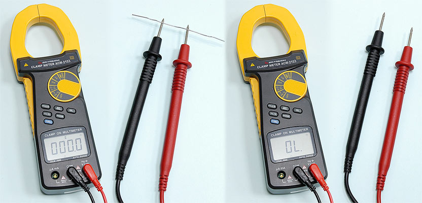
| ACM-2103 Clamp Meter - Diode Test |
|
|
| ACM-2103 Clamp Meter - Continuity Check |
|
|
Controls of ACM-2103 Clamp Meter
AC Current Measurement
Clamp on:
- Select "Function rotary switch" to the "2000A" position then push "FUNC" button, the display will show "~"
- Press the "Trigger" to open the "Current Sensor Jaws" and clamp on the measure conductor only.
Consideration:
a. Recommend use the "auto range" mode typically. However if push the "Range button" will hold the range.
b. For safety reason, please insert the "Terminal rubber cover" for protection.
Direct input:
- Connect BLACK test lead into "COM" terminal
- Connect RED test lead into "μA, mA" terminal
- If measure "μA" (400μA, 4000μA), select the "Function rotary switch" to the "μA" position then push the "FUNC" button, the display will show "~"
- If measure "mA" (40mA, 400mA), select the "Function rotary switch" to the "mA" position then push the "FUNC" button, the display will show "~"
- Open the circuit in which the current are to be measured. Now securely connect test lead in series with the circuit.

DC Current Measurement
Clamp on:
- Select the "Function rotary switch" to "2000A" position then push the "FUNC" button, the display will show "="
- Push the "DCA zero" button at least 2 seconds to let the display show "ZERO" value
- Press the "Trigger" to open the "Current Sensor Jaws" and clamp on the measure conductor only.
Consideration:
a. Recommend use the "auto range" mode typically. However if push the "Range button" will hold the range.
b. For safety reason, please insert the "Terminal rubber cover" for protection.
Direct input:
- Connect BLACK test lead into "COM" terminal
- Connect RED test lead into "μA, mA" terminal
- If measure "μA" (400μA, 4000μA), select the "Function rotary switch" to the "uA" position then push the "FUNC" button, the display will show "="
- If measure "mA" (40mA, 400mA), select the "Function rotary switch" to the "mA" position then push the "FUNC" button, the display will show "="
- Open the circuit in which the current are to be measured. Now securely connect test lead in series with the circuit.

DCV, ACV Measurement
- Connect BLACK test lead into "COM" terminal
- Connect RED test lead into "V" terminal
- When measuring "DCV" select the "Function rotary switch" to the "V" position then push the "FUNC" button, the display will show "="
- When measuring "ACV" select the "Function rotary switch" to the "V" position then push the "FUNC" button, the display will show "~"
- When LCD shows the "AUTO" marker the meter is under the "auto range" mode, the meter will select the suitable measurement range automatically
- Under the operation of "auto range" mode push the "Range button" will hold the range.
 
Capacitance Measurement
- Connect BLACK test lead into "COM" terminal.
- Connect RED test lead into "
 " terminal. " terminal.
- Select the "Function rotary switch" to the "" position then push the "Function button" for display show "nF"
- Zero adjustment:
Due to the consideration of the existing "stray capacitance" of the internal circuit board or the test aliigator. For the 50 nF & 500 nF range, it should to make the zero adjustment procedures before make the measurement first. Open the input terminal & not connecting the measured capacitor, push the "REL. Button", the display will show zero value. Then connect the measuring capacitor again & make the measurement following.
- For the capacitance measurement, the meter is always under the "auto range" mode, it will select the suitable measurement range automatically.

Resistance Measurement
- Connect BLACK test lead into "COM" terminal
- Connect RED test lead into "Ω" terminal
- Select the "Function rotary switch" to the "Ω" position then push the "FUNC" button, the display will show "Ω"
- When LCD shows the "AUTO" marker the meter is under the "auto range" mode, the meter will select the suitable measurement range automatically
- Under the operation of "auto range" mode push the "Range button" will hold the range.

Frequency and Duty Cycle Measurement
- Connect BLACK test lead into "COM" terminal.
- Connect RED test lead into "Hz" terminal.
- Select the "Function rotary switch" to the "Hz" position then push the "Hz/% button" for display show "Hz".
- For the FREQUENCY measurement, the meter is always under the "auto range" mode, it will select the suitable measurement range automatically.
- For the Duty Cycle measurement all the measuring procedures are same as above except push the "Hz/%" for display show "%".

Back light Operation
Push the " button" about two seconds continuously, the LCD back light lamp will turn on. button" about two seconds continuously, the LCD back light lamp will turn on.
Continuity Check
- Connect BLACK test lead into "COM" terminal.
- Connect RED test lead into "Ω" terminal.
- Select the "Function rotary switch" to the "
 " position then push the "FUNC. button" for display show "". " position then push the "FUNC. button" for display show "".
- When the resistance value is less than 10Ω, the beeper sound will be generated.
Data Hold Operation
- During the measurement, pushing the "Hold button" once a while will freeze the measured value & the LCD will indicate "H" symbol.
- Push the " Hold Button " again to release the data hold function.
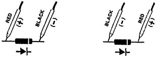
Diode Test
- Connect BLACK test lead into "COM" terminal.
- Connect RED test lead into "
 " terminal. " terminal.
- Select the "Function rotary switch" to the "" position then push the "FUNC. button" for display show "".
- a. When connected with polarity as shown in Fig. below, a forward current flow is established and the approx. Diode Forward Voltage (VF) value in volt will appears on the display reading. If the diode under test is defective, ".000" or near ".000" value (short circuit) or "1" (open circuit) will be displayed.
b. When connected as shown in Fig. below, a reverse check on the diode is made. If the diode under test is good," 1" will be displayed. If the diode under test is defective, ".000" or other numbers will be displayed. Proper diode testing should include both steps a. and b. above.

Relative Operation
- During the measurement, the circuit will memorize the last measured values if push the "REL.Button" at once, then LCD will show zero value & a "REL" indicator.
- The input measured values will deduct last measured values automatically, then show those new value on the display.
- It will release the Relative Measurement function if push the REL. button at once again, at same time the "REL" marker will disappear.
Back to the section
|
|