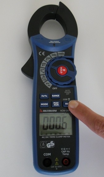
AKTAKOM ACM-2056W Professional AC, AC/DC True RMS Autoranging Clamp Meters with Wireless USB Interface
Features:
- Double molded plastic housing
- True RMS measurement for ACV & ACA
- Auto Power Off
- Current measurement: AC/DC
- LCD display counts: 6000
- AC True RMS
- Display with backlight
- Data Hold
- REL (Zero) Function
- Auto Power Off
- Low battery indication
- Analog Bargraph / 61 seg.
- 1.57” (40mm) Jaw opening
- USB interface
- Wireless transmitter: 915MHz
- Receive Sensitivity: -109dBm
- Communication Distance: ≤ 100m in an unobstructed field
Specifications:
|
Function
|
Max Range
|
Basic Accuracy
|
|
Voltage DC
|
600V
|
±(0.5%+1d)
|
|
Voltage AC
|
600V
|
±(1.5%+2d)
|
|
Current DC
|
1000A
|
±(2.0%+5d)
|
|
Current AC
|
1000A
|
±(2.5%+4d)
|
|
Resistance
|
60MΩ
|
±(3.0%+5d)
|
|
Temperature
|
1000ºC/ 1832°F
|
±(3.0%+3d)
|
|
Capacitance
|
4000μF
|
±(2.5%+5d)
|
|
Frequency
|
10MHz
|
±(1.2%+2d)
|
|
Continuity check
|
Buzzer sounds at 50Ω
|
|
Diode test
|
Test current 0.3mA
|
Size(HxWxD): 9,1in × 3,in × 1,6in / 230mm × 76mm × 40mm
Weight: 11,11oz / 315g
Accessories
Included
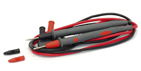
1. Test leads
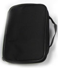
2. Carrying case
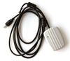
3. Wireless device with USB cable
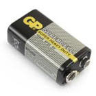
4. 9V battery
Optional
1. Software (Available for download by registration)

Testing Diode and Continuity Test
- Insert the black test lead banana plug into the negative COM jack and the red test lead banana plug into the positive diode jack.
- Turn the rotary switch to the Ω "diode", "Buzz" CAP position.
- Press the MODE button until "diode" appears in the display.
- Touch the test probes to the diode under test. Forward voltage will indicate 0.4V to 0.7V. Reverse voltage will indicate "OL". Shorted devices will indicate near OmV and an open device will indicate "OL" in both polarities.
For Continuity tests, if the resistance is <40Ω, a tone will sound.


Frequency / Duty Cycle Measurements (electronic)
- Set the rotary function switch to "V" position.
- Select ACV with the MODE button
- Press the Hz/% button to indicate "Hz" in the display.
- Insert the black lead banana plug into the negative COM jack and the red test lead banana plug into the positive Hz jack.
- Touch the test probe tips to the circuit under test.
- Read the frequency on the display.
- Press the Hz/% button again to indicate "%" on the display. Read the % of duty cycle on the display.


AC/DC Current Measurements
Warning: Ensure that the test leads are disconnected from the meter before making current clamp measurements.
- Set the Function switch to the 1000ADC, 600ADC, 1000AAC or 600AAC range.
- If the range of the measured is not known, select the higher range first then move to the lower range if necessary.
- Press the trigger to open jaw. Fully enclose one conductor to be measured. The clamp meter LCD will display the reading.

Capacitance Measurement
Warning: To avoid electric shock, disconnect power to the unit under test and discharge all capacitors before taking any capacitance measurements. Remove the batteries and unplug the line cords.
- Set the rotary function switch to the Ω "diode", "Buzz" CAP position.
- Insert the black test lead banana plug into the negative (COM) jack. Insert the red test lead banana plug into the positive (V) jack.
- Touch the test leads to the capacitor to be tested.
- Read the capacitance value in the display.

DC/AC Voltage Measurements
- Insert the black test lead into the negative COM terminal and the red test lead into the positive V terminal.
- Set the function switch to the V position.
- Select AC or DC with the MODE button.
- Connect the test leads in parallel to the circuit under test.
- Read the voltage measurement on the LCD display.


Non-Contact AC Voltage Measurements
Warning: Risk of Electrocution. Before use, always test the Voltage Detector on a known live circuit to verify proper operation.
- Touch the probe tip to the hot conductor or insert into the hot side of the electrical outlet.
- If AC voltage is present, the detector light will illuminate. NOTE: The conductors in electrical cord sets are often twisted. For best results, rub the probe tip along a length of the cord to assure placing the tip in close proximity to the live conductor.
NOTE: The detector is designed with high sensitivity. Static electricity or other sources of energy may randomly trip the sensor. This is normal operation.
Resistance Measurement
- Insert the black test lead into the negative COM terminal and the red test lead into the positive terminal.
- Set the function switch to the Ω "diode", "Buzz" CAP position.
- Touch the test probe tips across the circuit or component under test. It is best to disconnect one side of the device under test so the rest of the circuit will not interfere with the resistance reading.
- For Resistance tests, read the resistance on the LCD display.

Temperature Measurement
Warning: To avoid electric shock, disconnect both test probes from any source of voltage before making a temperature measurement.
- Set the function switch to TEMP.
- Insert the Temperature Probe into the negative (COM) and the V jacks, making sure to observe the correct polarity.
- Select °C or °F with the MODE button.
- Touch the Temperature Probe head to the part whose temperature you wish to measure. Keep the probe touching the part under test until the reading stabilizes (about 30 seconds).
- Read the temperature in the display. The digital reading will indicate the proper decimal point and value.
Warning: To avoid electric shock, be sure the thermocouple has been removed before changing to another measurement function.