|
|
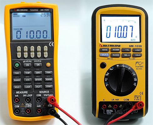
AM-7025 Process Calibrator
AM-7025 Process Calibrator
|
|
Multifunctional process calibrator multimeter. Double 5 digit LCD (50000 counts). The basic error: 0.02%. DC voltage measurement: 1µV...50V; DC: 1µA...50mA; resistance: 1Ω...5.5kΩ; frequency: 0.1Hz...10kHz; temperature (thermocouples of R-, S-, K-, E-, J-, T-, N-, B-types), thermistor (PT100, PT1000, PT200, PT500, Cu10, Cu50). Output characteristics: DC voltage: 1µV...11V; DC: 1µA...22mA; analog converter: 1µA...-20mA; resistance: 0.01Ω...40kΩ; frequency: 0.1Hz...100kHz; pulse mode: 100Hz / 1kHz / 10kHz / 100kHz; commutation: 0.1Hz...100kHz; temperature (thermocouples of R-, S-, K-, E-, J-, T-, N-, B-types), thermistor (PT100, PT1000, Cu50); loop power: 24V; pressure: 2.49kPa...70MPa. Continuity test, adjustable backlight (0...9000s). Power: 4 x 1.5V (AAA). Dimensions: 205x95x42mm / 8.07x3.7x1.7in, Weight: 500g / 17.6oz.
Manuals:
|
|
AKTAKOM AM-7025 multifunctional process calibrators are designed to generate high-precision signals when testing and calibrating different types of equipment (probes, measurers, converters, controllers etc.) during repair or adjustment work. These compact handheld devices are necessary for service engineers, they save time and solve a wide range of tasks in field conditions.
Specifications
Calibrator
|
Function
|
Range
|
Resolution
|
Accuracy
|
|
DC Voltage
|
100mV
1000mV
10V
|
-10.000…110.000mV
-100.00…1100.00mV
-1.0000…11.0000V
|
1μV
10μV
0.1mV
|
±(0.02%+10)
|
|
DC Current
|
20mA
|
0.000mA…22.000mA
|
1μA
|
±(0.02%+10)
|
|
Resistance
|
400Ω
4kΩ
40kΩ
|
400.00Ω
4.0000kΩ
40.000kΩ
|
0.01Ω
0.1Ω
1Ω
|
±(0.02%+10)
±(0.05%+10)
±(0.1%+10)
|
|
Frequency
|
100Hz / 1kHz
10kHz / 100kHz
|
110.0Hz / 1.100kHz /
11.0kHz / 110kHz
|
0.01Hz / 1Hz
0.1kHz / 2kHz
|
±2
|
|
Pulse
|
100Hz/ 1kHz
10kHz/100kHz
|
10…100000
|
1
|
±2
|
|
Switch
|
100Hz / 1kHz
10kHz / 100kHz
|
110.0Hz / 1.100kHz /
11.0kHz / 110kHz
|
0.01Hz / 1Hz
0.1kHz / 2kHz
|
±2 / ±2
±2 / ±5
|
|
Thermocouple
|
R, S
|
0…100…1767°C
|
1 °C
|
1.5°C / 1.2°C
|
|
B
|
400…600…800…1820°C
|
2.0°C /1.5°C / 1.1°C
|
|
E
|
-200.0…-100.0…600.0…1000.0°C
|
0.1 °C
|
0.6°C / 0.5°C / 0.4°C
|
|
K
|
-200.0…-100.0…400.0…1200.0…1372.0°C
|
0.6°C / 0.5°C / 0.7°C / 0.9°C
|
|
J
|
-200.0…-100.0…800.0…1200.0°C
|
0.6°C / 0.5°C / 0.7°C
|
|
T
|
-250.0 °C…400.0°C
|
0.6°C
|
|
N
|
-200.0…-100.0…900.0…1300.0°C
|
1.0°C / 0.7°C / 0.8°C
|
|
Thermistor
|
Pt100
|
-200.0…0.0…400.0…850.0°C
|
0,1 °C
|
0.3°C / 0.5°C/ 0.8°C
|
|
Pt1000
|
-200.0…100.0…300.0…630.0°C
|
0.2°C / 0.3°C / 0.4°C
|
|
Cu50
|
-50.0…150.0°C
|
0.6°C
|
|
Loop power
|
24V
|
|
|
±10%
|
|
Pressure
|
70MPa
|
2.49kPa…70MPa
|
|
0.025%-0.05%
|
Multimeter
|
Function
|
Range
|
Resolution
|
Accuracy
|
|
DC Voltage
|
50mV
500mV
5V
50V
|
-5.000…55.000mV
-10.00…550.00mV
-0.1000…5.5000V
0.00…55.00V
|
1μV
10μV
0.1mV
10mV
|
±(0.02%+10)
±(0.02%+2)
±(0.02%+5)
±(0.03%+5)
|
|
DC Current
|
50mA
|
-5.000…50.000mA
|
1μA
|
±(0.02%+2)
|
|
Resistance
|
500Ω (1mA)
5kΩ (0.1mA)
|
0.00Ω…550.00Ω
0.0000kΩ…5.5000kΩ
|
0.01Ω
0.1Ω
|
±(0.02%+0,1Ω)
±(0.02%+0,5Ω)
|
|
Continuity test
|
500Ω
|
≤ 50Ω
|
0.01Ω
|
|
|
Frequency
|
100Hz/ 1kHz/ 10kHz
|
110.0Hz / 1.100kHz / 1.0…11.0kHz
|
0.01Hz / 1Hz/ 0.1kHz
|
±2
|
|
Thermocouple
|
R, S
|
0…500…1767°C
|
1°C
|
1.8°C / 1.5°C
|
|
B
|
600…800…1000…1820°C
|
2.2°C / 1.8°C / 1.4°C
|
|
E
|
-50.0…0.0…1000.0°C
|
0.1°C
|
0.9°C / 1.5°C
|
|
K
|
-100.0…0.0…1372.0°C
|
1.2°C / 0.8°C
|
|
J
|
-60.0…0.0…1200.0°C
|
1.0°C / 0.7°C
|
|
T
|
-100.0°C…0.0…400.0°C
|
1.0°C / 0.7°C
|
|
N
|
-200.0…0.0…1300.0°C
|
1.5°C / 0.9°C
|
|
Thermistor
|
Pt100
|
-200.0…0.0…400.0…850.0°C
|
0.1°C
|
0.5°C / 0.7°C / 0.8°C
|
|
Pt200
|
-200.0…100.0…300.0…630.0°C
|
0.8°C / 0.9°C / 1.0°C
|
|
Pt500
|
0.4°C / 0.5°C / 0.7°C
|
|
Pt1000
|
0.2 °C / 0.3°C / 0.4 °C
|
|
Cu10
|
-100.0…260.0°C
|
1.8°C
|
|
Cu50
|
-50.0…150.0°C
|
0.7°C
|
- Double 5 digit LCD (50000 counts)
- The basic error: 0.02%
- Continuity test
- Adjustable backlight (0...9000s)
- Power: 4 x 1.5V (AAA)
- Auto power off function which can be disabled
- Dimensions: 205x95x42mm / 8.07x3.7x1.7in
- Weight: 500g / 17.6oz
Accessories
1. AM-7025 Process Calibrator
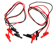
2. Red and Black Test leads: 2 pairs
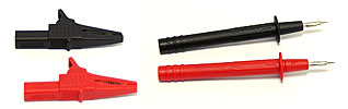
3. Probe tips (1 pair) and alligator clips (1 pair)
4. Case

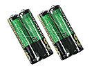
5. Triple-A Batteries: 1.5 V - 4 pcs
6. Instruction Manual

| AM-7025 Process Calibrator - front view |
|
|
| AM-7025 Process Calibrator - fuse |
|
|
| AM-7025 Process Calibrator - holster |
|
|
|
| AM-7025 Process Calibrator - accessories |
|
|
Measuring DC Current
- Make sure the lead cables for measurement are not connected to the measuring instrument under test.
- Using the function selector switch (FUNC), select DC Current measurement function.
- Connect the lead cables for measurement to the measuring terminals of the measuring instrument under test.
- The selected function and the measured value and unit shall be shown in the upper part of the LCD.

Measuring DC Voltage
- Make sure the lead cables for measurement are not connected to the measuring instrument under test.
- Using the function selector switch (FUNC), select DC Voltage measurement function.
- Connect the lead cables for measurement to the measuring terminals of the measuring instrument under test.
- Using the (RANGE) key, select a desired range from 50mV, 500mV, 5V, 50V. The selected function and the measured value and unit shall be shown in the upper part of the LCD.

Measuring Frequency
- Make sure the lead cables for measurement are not connected to the measuring instrument under test.
- Using the function selector switch (FUNC), select frequency measurement function.
- Connect the lead cables for measurement to the measuring terminals of the measuring instrument under test.
- Using the measurement (RANGE) key, select the suitable range from 500Hz, 5kHz, 50kHz. The selected function and the measured value and unit shall be shown in the upper part of the LCD.
Tips: The frequency measurement function is unavailable if the frequency, pulse, contact or pressure source function is on, which is only usable when the calibrator is in non-frequency, pulse, contact or pressure source function.

Measuring Resistance
- Make sure the lead cables for measurement are not connected to the measuring instrument under test.
- Using the function selector switch (FUNC), select resistance measurement function.
- Connect the lead cables for measurement to the measuring terminals of the measuring instrument under test.
- Using the measurement (RANGE) key, select the desired range from 500Ω, 5kΩ.The selected function and the measured value and unit shall be shown in the upper part of the LCD.

Measuring Continuity
Continuity measurement is used to detect the intactness of the circuit (e.g. a resistance lower than 50). Using the function selector switch (FUNC), select continuity measurement function. LCD displays continuity symbol " " on the upper part. Connecting the devices, the beeper sounds continuously if the loop circuit resistance under measurement is less than 50Ω,and LCD shows the present measured resistance value. " on the upper part. Connecting the devices, the beeper sounds continuously if the loop circuit resistance under measurement is less than 50Ω,and LCD shows the present measured resistance value.

Measuring Pressure
Ranges and types of the pressure module have various options. Due to the difference in medium and accuracy of different pressure modules, user needs to read the Manual before operating it. Real pressure module can work as a surface pressure module by opening the L input terminal exhausting the air. Follow the steps listed below to connect the tested technical pressure pipe with a proper pressure module.
 Warning Warning
To avoid a sudden release of the pressure system, do shut off the valve to release the pressure gradually before connecting the pressure module with the pipe.
Caution
- To avoid any mechanical damage to the pressure module, do not apply any force higher than 13.5Nm (10 ft.1bs) to the pressure pipe mouths(or the module and the pipe mouth). Do apply the specified force when connecting the pipe or the adapter.
- To avoid any damage to the pressure module due to over pressed, do not apply any pressure higher than the maximum value marked or specified.
- To avoid any corrosive damage, use the pressure module only with specified materials. Refer to the printing on the pressure module or the pressure module instruction sheet for the acceptable material compatibility.
- Connect the pressure module and calibrator. The screw of the pressure module pipe is compatible to the 1/4 inch NPT connector. If you have other requirement, contact the vendor.
- Using the function selector switch (FUNC), select the pressure measurement function. The calibrator connects and senses the type of the pressure module and sets the range automatically. If it fails to connect, the LCD shows "NO.OP" in the upper part.
- Zero off the reading following the pressure module manual. When the reading overtops the 95 percentage of maxim value of the range, the LCD shows "ERR" in the lower part. Pressing the (AVG) key initializes the calibrator to 0, and "Δ" symbol shows on the left upper part of the LCD.
Tips:
- For absolute pressure module, the calibrator saves the zero-off value and reuses the value automatically. Therefore, user does not need to zero off the calibration value for each use.
Measuring switch
The calibrator could measure the connection or disconnection signal of the switch. Using the function selector switch (FUNC), select switch measurement function. LCD displays switch symbol " " on the upper part. The beeper sounds for one second if the state of the switch under measurement is changing. " on the upper part. The beeper sounds for one second if the state of the switch under measurement is changing.
Measuring Temperature with RTD
- Make sure the lead cables for measurement are not connected to the measuring instrument under test.
- Using the function selector switch (FUNC), select RTD measurement function.
- Connect the lead cables for measurement to the measuring terminals of the measuring instrument under test
- Using the measurement (RANGE) key, select a desired range from PT100, PT200, PT500, PT1000, Cu10, C50. The selected function and the default measured value and unit shall be shown in the lower part of the LCD.
Tips:
- The RTD measurement function is unavailable if the TC/RTD source function is on, which is only usable when the calibrator is in non-TC or RTD source function.
- The calibrator defaults the 3-wire connection method when measuring RTD. When applying the 2-wire connection method, connecting the same RTD measurement. Pay special attention to linking the "COM" and "LOOP" terminals, otherwise, there would be a big error.
Measuring Temperature with Thermocouple (TC)
Note: Any voltage higher than 60V won’t work on the measured circuit if applying the thermocouple convertor to the given input terminal.
- Make sure the lead cables for measurement are not connected to the measuring instrument under test.
- Using the function selector switch (FUNC), select TC measurement function. Using the measurement (RANGE) key, select the desired range from K, E, J, T, B, N, R, S.
- Connect the thermocouple convertor to the jack under test.The selected function and the measured value and unit shall be shown in the upper part of the LCD.
Tips:
- The TC measurement function is unavailable if the TC/RTD source function is on, which is only usable when the calibrator is in non-TC/RTD source function.
- If there has been a sudden change in the operating ambient temperature of the calibrator, wait until the built-in reference junction compensation stabilizes. Avoid using the calibrator in locations exposed to wind from such apparatus as an airconditioner.
Sourcing Contact Output
You can turn on or off the output terminals by using the contact output function. An FET is used as the contact-switching device.
- Using the function selector switch (FUNC), select the contact output source function. The LCD shows the default value 10Hz, and the "" symbol.
- Using the (RANGE) key, select the desired frequency from 100Hz, 1kHz, 10kHz, and 100kHz.
- Set the output value digit by digit using each pair of (↑)/(↓) output setting keys. Each pair of (↑)/(↓) keys corresponds to each digit of the LCD reading. Each press of the (↑)/(↓) key increases or decreases the digit. Increasing the digit from 9 or decreasing it from 0 causes the digit to overflow or underflow, allowing you to set the output value without interruption. Holding down the (↑)/(↓) key continuously changes the digit. And the value won’t change if it is increased or decreased to the Maxim or Minimum value.
- Pressing the (ON) key causes the SOURCE indicator on the LCD to change from "OFF" to "ON".
- To turn off the output, press the (ON) key once again. The "OFF" appears on the LCD and no signals sourced between the terminals.
Tips:
- The contact output source function is unavailable if the frequency measurement function is on, which is only usable when the calibrator is in non-frequency measurement function.
- You cannot set the amplitude and pulse number in contact output function.
- The contact output is polarity. Generally, connect the positive polarity with the H jack of the calibrator and the negative polarity with the L jack.
- Note the maxim allowable current of the contact output is 50mA.
Sourcing DC Current
- Using the Function selector switch (FUNC) to select the desired source function 20mA .The default value and unit of the selected source function shall be displayed in the lower part of the LCD.
- Set the output value digit by digit using (↑) / (↓) keys. Each pair of (↑) / (↓) keys corresponds to each digit of the LCD reading. Each press of the (↑) / (↓) key increases or decreases the digit. Increasing the digit from 9 or decreasing it from 0 causes the digit to overflow or underflow, allowing you to set the output value without interruption. Holding down the (↑) / (↓) key continuously changes the digit in question. And the value won’t change if it is increased or decreased to the Maxim or Minimum. Pressing the〔ZERO〕key initializes the output set point to the default value (0).
- Pressing the (ON) key causes the indicator on the LCD to change from "OFF" to "ON". The calibrator sources the preset DC voltage between the output terminals.
- To turn off the output, press the (ON) key once again. The "OFF" appears on the LCD and no signals sourced between the terminals.

Sourcing DC Voltage
- Using the Function selector switch (FUNC) to select DC voltage source function, select the desired range from 100mV, 1V, and 10V by pressing the (RANG) key. The default value and unit of the selected source function and range shall be displayed in the lower part of the LCD.
- Set the output value digit by digit using (↑)/(↓) keys. Each pair of (↑)/(↓) keys corresponds to each digit of the LCD reading. Each press of the (↑)/(↓) key increases or decreases the digit. Increasing the digit from 9 or decreasing it from 0 causes the digit to overflow or underflow, allowing you to set the output value without interruption. Holding down the (↑)/(↓) key continuously changes the digit in question. And the value won’t change if it is increased or decreased to the Maxim or Minimum value. Pressing the (ZERO) key initializes the output set point to the default value (0).
- Pressing the (ON) key causes the indicator on the LCD to change from "OFF" to "ON". The calibrator sources the preset DC voltage between the output terminals.
- To turn off the output, press the (ON) key once again. The "OFF" appears on the LCD and no signals sourced between the terminals.

Sourcing Frequency
The calibrator can source a constant pulse signal responding to the preset frequency and amplitude.
- Using the function selector switch (FUNC), select frequency source function. The LCD shows the default frequency value10Hz and the frequency symbol in the lower part.
- Using the (RANGE) key, select a desired frequency range from 100Hz, 1kHz, 10Hz, 100kHz. The selected function and the default range source value and unit shall be shown in the lower part of the LCD.
- Set the output value digit by digit using each pair of (↑)/(↓) output setting keys. Each pair of (↑)/(↓) keys corresponds to each digit of the LCD reading. Each press of the (↑)/(↓) key increases or decreases the digit. Increasing the digit from 9 or decreasing it from 0 causes the digit to overflow or underflow, allowing you to set the output value without interruption. Holding down the (↑)/(↓) key continuously changes the digit. And the value won't change if it is increased or decreased to the Maxim or Minimum value.
- Pressing the (VPEAK) key once switches to amplitude setting mode. The LCD provides a reading of 1V.
- Set the output value digit by digit using each pair of (↑)/(↓) output setting keys. Each pair of (↑)/(↓) keys corresponds to each digit of the LCD reading. Each press of the (↑)/(↓) key increases or decreases the digit. Increasing the digit from 9 or decreasing it from 0 causes the digit to overflow or underflow, allowing you to set the output value without interruption. Holding down the (↑)/(↓) key continuously changes the digit. And the value won't change if it is increased or decreased to the Maxim or Minimum value.
- To re-enter into the frequency set mode, press the (FREQ) key to set the frequency.
- Pressing the (ON) key causes the SOURCE indicator on the LCD to change from "OFF" to "ON". The calibrator sources constant pulse signals responding to the preset frequency and amplitude between the output terminals.
- To turn off the output, press (ON) once again. The "OFF" appears on the LCD and no signals sourced between the terminals.
Tips:
- The frequency source function is unavailable if the frequency measurement function is on, which is only usable when the calibrator is in non-frequency measurement function.
- The frequency range could only be changed by pressing (RANGE) key in the frequency set mode.
- The frequency value and range could be changed when the frequency source function is both in "ON" or "OFF" state.

Sourcing Number of Pulses
The calibrator can source a preset number of pulse signal responding to the preset frequency and amplitude.
- Using the function selector switch (FUNC), select pulse source function. The LCD shows the default value 10Hz and the number of pulses mark in the lower part.
- Using the (RANGE) key, select a desired frequency range from 100Hz, 1kHz, 10Hz. The selected function and the default range source value and unit shall be shown in the lower part of the LCD.
- Set the output value digit by digit using each pair of (↑)/(↓) output setting keys. Each pair of (↑)/(↓) keys corresponds to each digit of the LCD reading. Each press of th (↑)/(↓) key increases or decreases the digit. Increasing the digit from 9 or decreasing it from 0 causes the digit to overflow or underflow, allowing you to set the output value without interruption. Holding down the (↑)/(↓) key continuously changes the digit . And the value won't change if it is increased or decreased to the Maxim or Minimum value.
- Pressing the (VPEAK) key once switches to amplitude setting mode. The LCD provides a reading of 1V.
- Set the output value digit by digit using each pair of (↑)/(↓) output setting keys. Each pair of (↑)/(↓) keys corresponds to each digit of the LCD reading. Each press of the (↑)/(↓) key increases or decreases the digit. Increasing the digit from 9 or decreasing it from 0 causes the digit to overflow or underflow, allowing you to set the output value without interruption. Holding down the (↑)/(↓) key continuously changes the digit. And the value won't change if it is increased or decreased to the Maxim or Minimum value.
- Pressing the (↑)/(↓) key ,enter into the pulse number set mode, and the LCD shows the default number of 1 CYC in the lower part.
- Set the output value digit by digit using each pair of (↑)/(↓) output setting keys. Each pair of (↑)/(↓) keys corresponds to each digit of the LCD reading. Each press of the (↑)/(↓) key increases or decreases the digit. Increasing the digit from 9 or decreasing it from 0 causes the digit to overflow or underflow, allowing you to set the output value without interruption. Holding down the (↑)/(↓) key continuously changes the digit. And the value won't change if it is increased or decreased to the Maxim or Minimum value.
- To re-enter into the frequency set mode, press the (↑)/(↓) key to set the frequency.
- Pressing the (ON) key causes the SOURCE indicator on the LCD to change from "OFF" to "ON", and the calibrator sources low level between the output terminals.
- Pressing the (START) key the calibrator sources the set number of pulse responding to the preset frequency and amplitude, LCD shows the symbol "RUN".
- When source is complete, the calibrator automatically turns off the output and ceases operation. The "RUN" symbol disappears from the LCD.
- To turn off the output, press the (ON) once again. The "OFF" appears on the LCD and no signals sourced between the terminals.
Tips:
- The contact output source function is unavailable if the frequency measurement function is on, which is only usable when the calibrator is in non-frequency measurement function.
- The frequency range of the pulse could only be changed by pressing (RANGE) key in the frequency set mode.
- When the "RUN" symbol vanishes from the LCD, you can change the frequency and amplitude both when the source function is in "ON" or "OFF".
- In the pulse sourcing process, pressing the (START) key causes to stop the output, and the "RUN" mark vanishes from the LCD. Press the (START) key once more to restart the sourcing function.
- Restarting the pulse output requires the source function is in "ON" state.
Sourcing Resistance
- Using the function selector switch (FUNC), select Ohm function. Using the (RANGE) key, select the desired range. The selected function and the default range source value and unit shall be shown in the lower part of the LCD.
- Set the output value digit by digit using each pair of (↑)/(↓) keys. Each pair of (↑)/(↓) keys corresponds to each digit of the LCD reading. Each press of the (↑)/(↓) key increases or decreases the digit. Increasing the digit from 9 or decreasing it from 0 causes the digit to overflow or underflow, allowing you to set the output value without interruption. Holding down the (↑)/(↓) key continuously changes the digit in question. And the value won’t change if it is increased or decreased to the Maxim or Minimum value. Pressing the (ZERO) key initializes the output set point to the default value (0).
- Pressing the (ON) key causes the SOURCE indicator on the LCD to change from "OFF" to "ON". The calibrator sources the preset resistance value between the output terminals.
- To turn off the output, press the (ON) key once again. The "OFF" appears on the LCD and no signals sourced between the terminals.
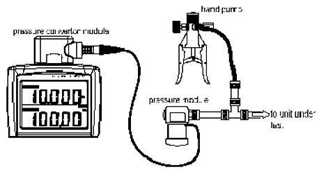
Sourcing Pressure
The calibrator source pressure by measuring the pressure from a pump or any other device, and shows the value in the lower part of the LCD. Figure below demonstrates how to connect the pump with the pressure module so as to make it into a calibrated source. Ranges and types of the pressure module have various options. Due to the difference in medium and accuracy of different pressure modules, user needs to read the Manual before operating it. Follow the steps listed below to source pressure with a proper pressure module (assisted by the tested technical pressure).
Warning
To avoid a sudden release of the pressure system, do shut off the valve to release the pressure gradually before connecting the pressure module with the pipe.
Caution
- To avoid any mechanical damage to the pressure module, do not apply any force higher than 13.5N•m to the pressure pipe mouths (or the module and the pipe mouth). Do apply the specified force when connecting the pipe or the adapter.
- To avoid any damage to the pressure module due to over pressed, do not apply any pressure higher than the maximum value marked or specified.
- To avoid any corrosive damage, use the pressure module only with specified materials. Refer to the printing on the pressure module or the pressure module instruction sheet for the acceptable material compatibility.
- Connect the pressure module and calibrator. The screw of the pressure module pipe is compatible to the ¼in NPT connector. If you have other requirement, contact the vendor.
- Using the function selector switch (FUNC), select the pressure source function. The LCD shows "OKPa" in the lower part.
- Pressing the ON key turns on the function, the calibrator connects and senses the type of the pressure module and sets the range automatically. If it fails to connect, the LCD shows "NO.OP" in the lower part.
- Zero off the reading following the pressure module manual. When the reading overtops the 95 percentage of maxim value of the range, the LCD shows "ERR" in the lower part. Pressing the (ZERO) key initializes the calibrator to 0, and "Δ" symbol shows on the left lower part of the LCD.
- Apply pressure on the pipe with the pressure source until the desired pressure value displayed on the LCD.
Tips:
- For absolute pressure module, the calibrator saves the zero-off value and reuses the value automatically. Therefore, user does not need to zero off the calibration value for each use.
- You cannot set the pressure value on the LCD in pressure source function.
Sourcing RTD
- Firstly, the calibrator sources a resistance signal by receiving the resistance-measuring current I supplied from the device being calibrated (such as a resistance meter) and then delivering the voltage V proportional to the preset resistance R between the output terminals, and thus producing the equivalent resistance R =V/I. Consequently, the calibrator sources the signal correctly only for such devices that employ this method of measurement.
- The allowable range of the resistance measuring current I that the calibrator receives from a resistance measuring device under calibration is rated as 0.1 to 3 mA. To ensure accuracy, the resistance measuring current I from the device under calibration shall be strictly confined within the range.
- Any resistance signal being sourced does not include the resistance component of the lead cables for source. The whole resistance, when measured at the ends of the lead cables for source, is given by adding the resistance of the lead cables (approximately 0.1 on a round-trip basis) to the sourced resistance signal. For source of precise resistance signals, use three-wire or four-wire connection.
- Using the function selector switch (FUNC), select RTD function. Using the (RANGE) key, select a desired RTD range from PT100, PT200, PT500, PT1000, Cu10, Cu50. The selected function and the default range source value and unit shall be shown in the lower part of the LCD.
- Set the output value digit by digit using each pair of (↑)/(↓) keys. Each press of the (↑)/(↓) key increases or decreases the digit. Increasing the digit from 9 or decreasing it from 0 causes the digit to overflow or underflow, allowing you to set the output value without interruption. Holding down the (↑)/(↓) key continuously changes the digit in question. And the value won’t change if it is increased or decreased to the Maxim or Minimum value. Pressing the (ZERO) key initializes the output set point to the default value (0).
- Pressing the (ON) key causes the SOURCE indicator on the LCD to change from "OFF" to "ON". The calibrator sources the preset resistance value between the output terminals.
- To turn off the output, press the (ON) key once again. The "OFF" appears on the LCD and no signals sourced between the terminals.
Tips: The RTD source function is unavailable if the TC/RTD measurement function is on, which is only usable when the calibrator is in non-TC or RTD measurement function.
Frequently Asked Questions
Does AKTAKOM AM-7025 process calibrator have auto power off function?
How can I deactivate Auto Power Off function of AKTAKOM AM-7025 process calibrator?
| Does AKTAKOM AM-7025 process calibrator have auto power off function? |
Yes, it does. There is Auto Power Off function in AM-7025 when operating in the measurer mode: the device power automatically goes off if you do not use the device within 5 minutes. If you would like to continue the work press POWER button.
Up
|
| How can I deactivate Auto Power Off function of AKTAKOM AM-7025 process calibrator? |
Enter “SPFC” additional settings mode of AM-7025 process calibrator. You will need to keep HOLD button pressed when powering on the device. The top right corner will display “SPFC” symbol. To deactivate auto power off function press MEASURE ON button in “SPFC” mode until you see “AP.OFF” on the display. (This function is displayed on default when entering the additional settings mode).
Specify auto power off time from 0 to 60 minutes by using the second pair of ⇓/⇑ keys (if counting from right to left). Every time you press ⇓/⇑ you increase or decrease the interval by 10 minutes. If you keep one of these keys pressed you continuously change the value, however this value won’t exceed the max. limit and won’t become lower the min. one.
To save the results press SOURCE ON button, “SAVE” symbol will be displayed for 1 second.
To automatically switch auto power off function specify “0”.
Up
|
Back to the section
|
|


