|
|
ACM-1010 Clamp Meter
|
|
Diameter of coverage is 42mm/1.7in. LCD display 1999 digits. Base accuracy 1%. Measurements: DC voltage up to 1000V, AC voltage up to 750V, AC current up to 20/200/1000A; Resistance up to 200Ω/2kΩ. Temperature -40°C…750°C. Audible continuity test, manual range selection, Data hold button, Backlighting.
Manuals:
|
|
Clamp meters AKTAKOM ACM-1010 are designed for non-contact alternate current measurement as well as AC/DC voltage, resistance and other measurements include temperature.
Features
- Audible continuity test
- Manual range selection
- Data hold button
- Backligt LCD display
Specifications
|
Function
|
Ranges
|
Basic Accuracy
|
|
Voltage DC
|
1000V
|
±(1.0%+2d)
|
|
Voltage AC
|
750V
|
±(1.2%+5d)
|
|
Current AC
|
20/200/1000A
|
±(2.0%+5d)
|
|
Resistance
|
200Ω/2kΩ
|
±(1.0%+3d)
|
|
Temperature
|
-40°C…750°C
|
±(1.0%+3d)
|
General specifications
- Diameter of coverage: 42mm/1.7in
- Display: LCD 1999 counts
- Supply: 3x1.5V (AAA)
Accessories
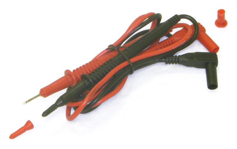
- Test leads
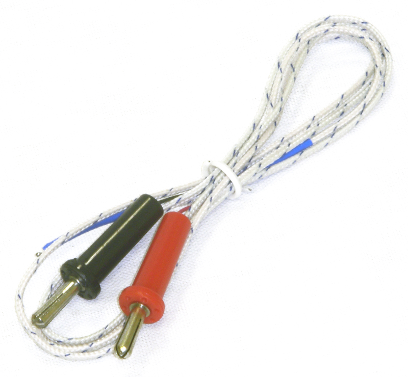
- Temperature probe
- User manual
| ACM-1010 Clamp Meter - front view |
|
|
| ACM-1010 Clamp Meter - left view |
|
|
| ACM-1010 Clamp Meter - right view |
|
|
|
| ACM-1010 Clamp Meter - with accessories |
|
|
| ACM-1010 Clamp Meter - test leads |
|
|
| ACM-1010 Clamp Meter - K-Type thermocouple |
|
|
|
| ACM-1010 Clamp Meter - DCV Measurement |
|
|
| ACM-1010 Clamp Meter - ACV Measurement |
|
|
| ACM-1010 Clamp Meter - ACA Measurement |
|
|
|
| ACM-1010 Clamp Meter - Resistance Measurement |
|
|
| ACM-1010 Clamp Meter - Continuity Check |
|
|
| ACM-1010 Clamp Meter - Temperature Measurement |
|
|
|
Controls of ACM-1010 Clamp Meter

AC Current Measurement
- Set the rotary switch at desired A
 position. position.
- Press the trigger to open transformer jaw and to clamp one conductor only, making sure that the jaw is firmly closed around the conductor.
- Read current value on LCD display.
- When only the figure "1" is displayed, it indicates overrange situation and the higher range has to be selected.

AC Voltage Measurement
- Connect the red test lead to the "V/Ω" jack and the black lead to the "COM" jack.
- Set rotary switch at desired 750V position.
- Connect test leads across the source or load being measured.
- Read voltage value on the LCD display.

DC Voltage Measurement
- Connect the red test lead to the "V/Ω" jack and the black lead to the "COM" jack.
- Set rotary switch at desired 1000V
 position. position.
- Connect test leads across the source or load being measured.
- Read voltage value on the LCD display along with the polarity of the red lead connection.

Resistance Measurement
- Connect the red test lead to "V/Ω" jack and black test lead to the "COM" jack (The polarity of red lead is positive "+").
- Set the rotary switch at desired "Ω" range position.
- Connect test leads across the resistor to be measured and read LCD display.
- If the resistance being measured is connected to a circuit, turn off power and discharge all capacitors before applying test probes.
NOTE:
- If the resistance being measured exceeds the maximum value of the range selected or the input is not connected, an overrange indication "1" will be displayed.
- When checking in-circuit resistance, be sure the circuit under test has all power removed and that all capacitors have been discharged fully.

Continuity test
- Connect red test lead to "V/Ω" jack, black test lead to "COM" jack.
- Set range switch to "
 " position. " position.
- Connect test leads to two points of circuit to be tested. If continuity exists, built-in buzzer will sound.

Temperature Measurement
- Set the rotary switch at 750 °C position.
- Connect the red lead of “K” type thermocouple into the "V/Ω" jack and the black lead of "K" type thermocouple into the "COM" jack. The LCD display will show the current environment temperature.
- Contacting the object be measured with the thermocouple probe.
- Read temperature value on the LCD display.

Frequently Asked Questions
How to measure AC voltage using ACM-1010 clamp meter?
How to make audible continuity test using ACM-1010 clamp meter?
How to measure AC current using ACM-1010 clamp meter?
How to measure DC voltage using ACM-1010 clamp meter?
How to measure resistance using ACM-1010 clamp meter?
How to measure temperature using ACM-1010 clamp meter?
| How to measure AC voltage using ACM-1010 clamp meter? |
- Connect the red test lead to “V/Ω” jack and the black test lead to the “COM” jack.
- Set the rotary switch at desired 750V~ position.
- Connect test leads across the source or load being measured.
- Read voltage value on the LCD display
Up
|
| How to make audible continuity test using ACM-1010 clamp meter? |
- Connect red test lead to “V/Ω” jack, black test lead to “COM” jack.
- Set range switch to “
 ” position. ” position.
- Connect test leads to two points of circuit to be tested. If continuity exists, built-in buzzer will sound.
Up
|
| How to measure AC current using ACM-1010 clamp meter? |
- Set the rotary switch at desired A∼ position.
- Press the trigger to open transformer jaw and to clamp one conductor only, making sure that the jaw is firmly closed around the conductor.
- Read current value on LCD display.
- When only the figure “1” is displayed, it indicates overrange situation and the higher range has to be selected.
Up
|
| How to measure DC voltage using ACM-1010 clamp meter? |
- Connect the red test lead to the “V/Ω” jack and the black lead to the “COM” jack.
- Set rotary switch at desired 1000V
 position. position.
- Connect test leads across the source or load being measured.
- Read voltage value on the LCD display along with the polarity of the red lead connection.
Up
|
| How to measure resistance using ACM-1010 clamp meter? |
- Connect the red test lead to “V/Ω” jack and black test lead to the “COM” jack (The polarity of red lead is positive “+”).
- Set the rotary switch at desired ”Ω” range position.
- Connect test leads across the resistor to be measured and read LCD display.
- If the resistance being measured is connected to a circuit, turn off power and discharge all capacitors before applying test probes.
Note:
- If the resistance being measured exceeds the maximum value of the range selected or the input is not connected, an overrange indication “1” will be displayed.
- When checking in-circuit resistance, be sure the circuit under test has all power removed and that all capacitors have been discharged fully.
Up
|
| How to measure temperature using ACM-1010 clamp meter? |
- Set the rotary switch at 750°C position.
- Connect the red lead of “K” type thermocouple into the “V/Ω” jack and the black lead of “K” type thermocouple into the “COM” jack. The LCD display will show the current environment temperature.
- Contacting the object be measured with the thermocouple probe.
- Read temperature value on the LCD display.
Up
|
Back to the section
|
|


