AC and DC Voltage measurement
Set the rotary switch to the position of V.
1 Press SELECT key to select between AC and DC voltage mode.
2 Connect the black and red test leads to the COM and V terminals respectively.
3 Connect the test leads tip in parallel with the circuit to be measured.
4 Read the voltage value on the main-display and read the frequency of AC signal on the sub-display.
Capacitance measurement
Capacitance is the ability of a component to store an electrical charge.
The unit of capacitance is the farad (F). Most capacitors are in the nanofarad to microfarad range. The Meter measures capacitance by charging the capacitor with a known current for a known period of time, measuring the resulting voltage, then calculating the capacitance. The measurement takes about 1 second per range.
To measure capacitance set up the Meter as shown in Figure:
1. Set the rotary switch to  range.
2. Connect the black and red test leads to the COM and terminals respectively.
3. Connect the test leads tip to the capacitor being measured.
4. Read the displayed value from LCD.
NOTE: The meter may take a few seconds to stabilize reading when measurement on 660μF…66mF. To improve the accuracy of measurements less than 660nF, subtract the residual capacitance of the Meter and leads.
 To avoid electrical shock and/or damage to the instrument, disconnect circuit power and discharge all high-voltage capacitors before measuring capacitance. Use the dc voltage function to confirm that the capacitor is discharged.
Continuity Check
1. Set the rotary switch to Ω range.
2. Press the SELECT key twice to activate Continuity Check.
3. Connect the black and red test leads to the COM and Ω terminals respectively.
4. Connect the test leads tip to the resistance in the circuit being measured.
5. When the test lead to the circuit is below 30Ω, a continuous beeping will indicate it.
Current measurement
To measure current set up the Meter as shown in Figure:
1. Turn off power to the circuit. Discharge all high voltage capacitors.
2. Set the rotary switch to the μA, mA or A range.
3. Press the SELECT key to select DCA or ACA measuring mode. (When measuring AC current, the sub-display will show the frequency of AC signal.)
4. Connect the black test lead to the COM terminal and the red test leads to the mA terminal for a maximum of 600mA. For a maximum of 10A, move the red test lead to the A terminal.
5. Break the circuit path to be tested. Touch the black probe to the more negative side of the break; touch the red probe to the more positive side of the break. (Reversing the leads will give a negative reading, but will not damage the Meter.)
6. Turn on power to the circuit; then read the display. Be sure to note the measurement units at the right side of the display (μA, mA or A). When only the figure "OL" displayed, it indicates overrange situation and the higher range has to be selected.
7. Turn off power to the circuit and discharge all high voltage capacitors. Remove the Meter and restore the circuit to normal operation.
 To avoid damage to the Meter or injury if the fuse blows, never attempt an in-circuit current measurement where the open-circuit potential to earth is greater than 1000V. To avoid damage to the meter, check the meter's fuse before proceeding. Use the proper terminals, function, and range for your measurement. Never place the probes in parallel with a circuit or component when the leads are plugged into the current terminals.
Diode Test
1. Set the rotary switch to Ω range.
2. Press the SELECT key once to activate Diode Test.
3. Connect the black and red test leads to the COM and VΩ terminals respectively.
4. For forward-bias readings on any semiconductor component, place the red test lead tip on the component's anode and place the black test lead tip on the component's cathode.
5. The meter will show the approx. forward voltage of the diode. If the polarity of test leads is reversed, "OL" will be displayed.
Frequency and Duty Cycle measurement
1. Set the rotary switch to the Hz range.
2. Insert the black and red test leads into the COM and Hz input terminals.
3. Connect the test leads tip in parallel with the circuit to be measured. And don’t touch any electrical conductors.
4. Read the frequency on the main-display and read the percent of duty cycle on the sub-display.
Resistance measurement
1. Set the rotary switch to Ω range.
2. Connect the black and red test leads to the COM and VΩ terminals respectively.
3. Connect the test leads tip to the circuit being measured.
4. Read the displayed value.
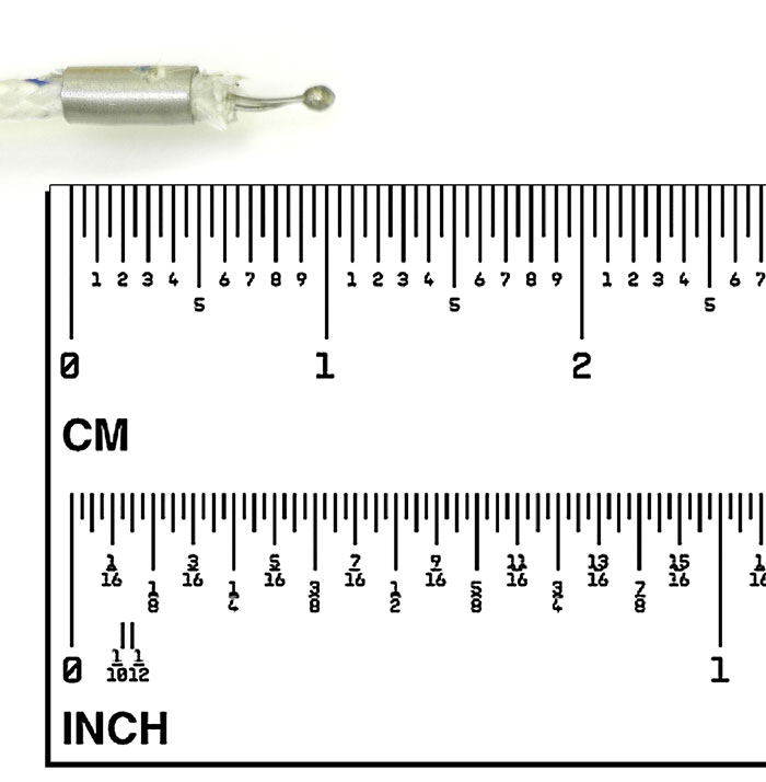
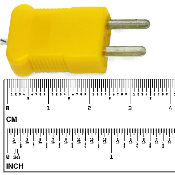
Temperature measurement
To measure temperature:
1. Set the rotary switch to °C°F range and the LCD will show the current environment temperature.
2. Press SELECT key to select °C or °F.
3. Insert ‘K’ type thermocouples into the COM terminal and °C terminal (or you can insert it by using Multi Function Socket). Takings care to observe the correct polarity.
4. Touch the object with the thermocouple probe for measurement.
5. Read the stable reading from LCD.
To avoid electrical shock and/or damage to the instrument, do not apply more than 250VDC or 220VAC rms between the °C terminal and the COM terminal. To avoid electrical shock, do not use this instrument when voltages at the measurement surface exceed 60VDC or 24V rms AC. To avoid damage or burns. Do not make temperature measurement in microwave ovens.