|
|||||
|
|
||||
|
|||||
|
|
||||
|
Search
Log in
|
AM-1108 Digital Multimeter
AM-1108 is a handled, battery-operated tool for measuring electrical parameters. It has all the features of a digital millimeter and measure AC voltage, DC voltage, AC current, DC current, resistance, capacitance, frequency, duty cycle ratio, dBm, TC, RTD, Diode Test, and Continuity Check. Features
Accessories1. Red and Black Test leads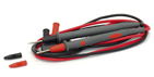 2. USB-cable 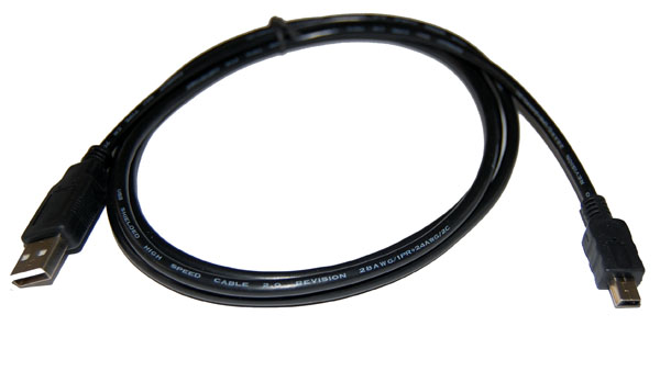 3. Software  4. Battery: 1.5V AAA x 4  5. Multimeter bag  6. Instruction Manual 
dBm Measurements in AC Volts FunctionsThe ac volts functions allow you to display readings as deviations in dB (decibels) above or below an established level. Set up dB measurements with the following procedure:
If dBm is displayed, check that thereference resistance value closely matches the impedance of the system being measured. dB is calculated with the following formula: dBm=20xlog10(Vx/Vr), For dBm, Vr is the voltage across the reference resistance at 1mW. For example, Vr would be 0.7746V with a 600Ω reference resistance. Measuring AC Voltage
Measuring DC Voltage
Measuring DC mV Voltage
Measuring Current
Caution
Notice
DC Current Mesurement
Measuring Capacitance
The meter’s capacitance ranges are 50.00nF, 500.0nF, 5.000μF, 50.00μF, 100.0μF.
Caution
Measuring Frequency and Duty Cycle RatioIn voltage and current (DC mV excluded) measurement, press Measuring Resistance
The meter’s resistance ranges are 400.0Ω, 4.000kΩ, 40.00kΩ, 400.0kΩ, 4.000MΩ and 40.00MΩ.
Measuring RTD
Measuring TC
When the output jack is open circuit, the screen displays OL. To avoid possible electric shock or personal injury, do not connect the TC with the live circuit. Testing Diodes
To avoid possible damage to the meter or to the equipment under test, disconnect circuit power and discharge all high-voltage capacitors before testing diodes. Use the diode test to check diodes, transistors, and silicon-controlled rectifiers (SCR), and other semiconductor devices. The test sends a current through a semiconductor junction, and then measures the junction’s voltage drop. A typical junction drops 0.5V to 0.8V. To test a diode, proceed as follows:
In a circuit, a similar diode should still indicate a forward bias reading of 0.5V to 0.8V; however, the reverse-bias reading can vary depending on the resistance of other pathways between the probe tips. Note
Testing for Continuity
Continuity is the presence of a complete path for current flow. The continuity test features a beeper that sounds if a circuit is
To test continuity, proceed as follows:
Frequently Asked Questions
Back to the section |
||||||||||||||||||||||||||||||||||||||||||||||