|
|
AM-1083 Digital Multimeter
AM-1083 Digital Multimeter
|
|
Digital multimeter, 3 ½ digit LCD (1999), the basic error of 0.5%. Measurement of DC voltage of 1000V ± (0.5%+3); AC voltage of 750V ± (0.8%+5); DC current of 20A ± (0.8%+3); AC current of 20A ± (1.0%+5) resistance of 2000MΩ ± (0.8%+3); capacitance up to 200µF ± (2.5%+20); inductance of 20H ± (2.5%+4); frequency of 10MHz ± (0.5%+4); temperature (K-type thermocouple) -20...1000°C ± (1.0%+4). Frequency range of 40...400Hz. Continuity test, diode test, hold readings, auto power off, backlight; MIN/MAX; protection against overload, misconnection and electric shock. Power: 9V. Dimensions: 189x97x35mm / 7.4x3.8x1.4in, weight: 400g / 14.1oz.
Manuals:
|
|
AKTAKOM AM-1083 is a stable and battery-driven 3 1/2 digital multimeter with high reliability. It adopts LCD screen with character height of 28mm; with functions including unit sign/backlight and overload protection, it is easy to use. This series of device can be used to measure DCV, ACV, DC, AC, resistance, capacitance, inductance, diode, triode, open circuit, temperature and frequency, as well as hold peak value. As an instrument with excellent performance it adopts double integral A/D converter as its core.
Features
- Display mode: LCD; Max display: 1999 (3 1/2) digits automatic polarity display.
- Measurement method: double integral A/D conversion.
- Sampling rate: about 3 time per second
- Over-range display: the highest digit displays "OL" or "-OL"
- Auto Power Off: can't be disabled
- Low voltage display
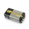
- Power supply: one 9V battery (6F22 or equivalent model);
- Dimension: 189x97x35mm / 7.4x3.8x1.4 in
- Weight: about 400g / 14.1oz (including 9V battery);
Accessories
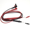
1. Red and Black Test leads
2. 9V battery (design may vary)
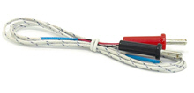
3. Thermocouple K-Type
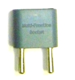
4. Input adapter
5. Instruction Manual
| AM-1083 Digital Multimeter - test leads |
|
|
| AM-1083 Digital Multimeter - input terminals |
|
|
| AM-1083 Digital Multimeter - front view |
|
|
|
| AM-1083 Digital Multimeter - thermocouple K-type |
|
|
| AM-1083 Digital Multimeter - holster |
|
|
| AM-1083 Digital Multimeter - accessories |
|
|
|
Controls of AM-1083 multimeter
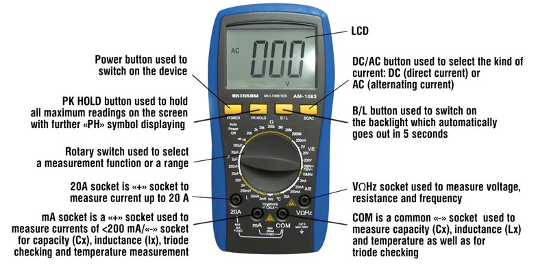
Voltage measurement
- Insert the black pencil into the "COM" jack, and the red one into the "V/Ω/Hz" jack;
- Turn the switch to position "V". If the level of voltage to be measured is unknown then select the biggest range and then decrease the range step by step until getting the value with the highest resolution.
- Popup the key "DC/AC" to enter into DC mode if measuring DC; Press down the key "DC/AC" to set into AC mode.
- The screen will show the voltage measured if touch the testing point using the pencils; the point touched by the red pencil is in positive voltage if the value showed is positive.
Notice:
- As showed, "OL" indicates the range is over and shall switch to a higher range.
- The voltage to be tested shall not over DC 1000V or AC 750V. The pencils shall be away from the testing point as switching functions or ranges.
- When measuring high voltage circuit, any parts of your body should not touch the high voltage circuit, otherwise it may hurt your body.
Current measurement
- Insert the black pencil into the "COM" jack, and the red one into the "mA" or "20A" jack.
- Turn the switch to position "A". If the level of current to be measured is unknown then select the biggest range and then decrease the range step by step until getting the value with the highest resolution.
- Popup the key "DC/AC" to enter into DC mode if measuring DC; press down the key "DC/AC" to set into AC mode.
- The screen will show the value of current measured if connect in parallel the pencil to the circuit to be tested; the point touched by the red pencil is in positive voltage if the value showed is positive.
Notice:
- As showed, "OL" indicates the range is over and shall switch to a higher range.
- The input in "mA" jack shall not over 200mA and "20A" not over 20A (less than 10 seconds of testing duration) as measuring current; the pencils shall be away from testing points as switching function or range.
Capacitance measurement
- Switch to a proper range, and insert pencils into "mA" and "com" jack.
- Connect the two pencils in parallel to the two ends of the capacitor. Please pay attention to the polarity, as the "com" for positive and "mA" for negative.
Notice:
- If capacitance exceeds the range selected, "OL" will be displayed in screen, then you shall increase the range by one step.
- The LCD may show some rudimental digits upon the starting of capacitance measurement. It’s normal and will not affect the testing result;
- If there is serious creepage or capacitor broken down in high capacitance range, the digits showed will be random and unstable.
- Please discharge capacitor completely to avoid device damage before measuring capacitance.
Inductance measurement
- Switch to a proper range, and insert pencils into "mA" and "com" jack.
- Bridge the pencils on the two ends of inductor.
Notice:
- If inductance exceeds the range selected, "OL" will be displayed in screen, then you shall increase the range by one step.
- The inductance value measured for identical inductor may be different if there is different impendence;
- If in range 2mH, please short pencils and measure lead inductance, and then subtract the inductance from the value measured.
- Avoid measuring small inductor in high range, or the accuracy is not guaranteed.
Resistance measurement
- Insert the black pencil into the "COM" jack, and the red one into the "V/Ω/Hz" jack;
- Turn the range switch to resistance position, then bride two pencils at the two ends of the resistor.
Notice:
- "OL" will be displayed in screen if the resistance is over the range, then you shall increase the range by one step;
- When input is open circuit, it will display status of overload;
- When measuring resistance on line, ensure that all power of circuit tested are turn down and all capacitor are discharged completely;
- Never input voltage if in resistance measurement mode!
- It normal for resistance higher than 1MΩ that the reading data is not stable for the first several seconds;
Frequency measurement
- Insert pencils or shielded cable into "COM" and "V/Ω/Hz" jack;
- Turn range switch to frequency position and bridge pencils or cables over the signal source or load tested.
Notice:
- The device can still work if the input is higher than 10V virtual value, but the accuracy is not guaranteed;
- In noise environment, you'd better use shield cable to measure small signal;
- When measuring high voltage circuit, any parts of your body should not touch the high voltage circuit, otherwise it may hurt your body.
- Never input voltage higher than 250V DC or AC peak value, otherwise it may damage your device.
Temperature measurement
Turn range switch to "°C", insert the cathode (black pin) of cold end (free end) of thermocouple into "mA" jack, anode (red pin) into "COM" jack, put the working end (temperature measurement end) of thermocouple on the surface or inside the object to be tested. Then you can read temperature from the screen, and the data is in centigrade.
Diode and open circuit test
- Insert the black pencil into "COM" jack, and the red one into the "V/Ω/Hz" jack (Notice: the red pencil is anode);
- Turn the range switch to position "
  ", connect pencils in parallel to the diode tested, with the red pencil to the anode and the black to cathode, then the reading value will be approximate forward voltage drop of the diode; ", connect pencils in parallel to the diode tested, with the red pencil to the anode and the black to cathode, then the reading value will be approximate forward voltage drop of the diode;
- Connect pencils to two points of the circuit to be tested, if buzzer sounds, then the resistance between the two points is lower than (70±20)Ω.
Transistor hFE Test
- Turn the range switch to "hFE" position;
- Insert testing accessory into "mA" and "com" jack. Please pay attention to the polarity, as the "com" for positive and "mA" for negative.
- To determine the triode's type, NPN or PNP, insert the emitting, base and collector electrode into the corresponding jacks in testing accessory.
Back to the section
|
|


