|
|
AM-1038 Professional Precision Digital Multimeter
AM-1038 Professional Precision Digital Multimeter
|
|
Professional handheld digital multimeter. Measurements: DC and AC voltage 0,001mV...1000V, DC and AC current 0,01μA...10A, Resistance 0,01Ω...50MΩ, Capacitance 0,01 nF...5000 µF; Basic accuracy 0,03%, True RMS, dBm, MAX/MIN, Relative measurements, bar graph indication and frequency measurement path (50 segments), Auto and manual measurement range selection, Backlit display, Auto turn-off, Optically isolated USB interface, Data hold. 50 000 counts display. Dimensions: 200x100x40mm. Weight 560 g.
Manuals:
|
|
The accuracy of professional multimeter AKTAKOM AM-1038 is 0.03%! It is designed to measure AC/DC, voltage, resistance, capacity, frequency, temperature and it can show dBm and allows data transfer to PC via optically isolated USB interface. If you need awesome multimeter, this multimeter is for you!
Features:
- Display: 50000 counts, bar graph indication and frequency measurement path (50 segments)
- Base accuracy 0.03%
- True RMS
- Resolution 0.01Ω (resistance meas.) and 1μV (voltage meas.)
- dBm measurements
- Min/Max, relative measurements
- Auto and manual measurement range selection
- Data hold
- Backlit display
- Auto turn-off
- USB 1.1 interface with galvanic isolation
Safety Conformance
- EN61010-1 CATIII 1000V
- 1000V input protection on all ranges
- 12.5A / 500V & 0.63A / 500V fuses protection on current ranges
Specifications:
|
Function
|
Range
|
Resolution
|
Accuracy
|
|
DC Voltage
|
50mV
|
0.001mV
|
(0.03% reading + 10 digits)
|
|
500mV
|
0.01mV
|
±(0.03% reading + 6 digits)
|
|
5V
|
0.0001V
|
|
50V
|
0.001V
|
|
500V
|
0.01V
|
|
1000V
|
0.1V
|
|
AC Voltage (AC+DC)
|
|
|
40Hz ... 1kHz
|
1kHz ... 10kHz
|
10kHz ... 20kHz
|
|
50mV
|
0.001mV
|
±(0.5% reading + 40 digits)
|
±(1% reading + 40 digits)
|
±(2.5% reading + 40 digits)
|
|
500mV
|
0.01 mV
|
|
5V
|
0.0001V
|
|
50V
|
0.001V
|
|
500V
|
0.01V
|
-
|
|
1000V
|
0.1V
|
-
|
-
|
|
All AC voltage ranges are specified from 10% of range to 100% of range
|
|
DC Current
|
500µA
|
0.01µA
|
±(0.15% reading + 15 digits)
|
|
5000µA
|
0.1µA
|
±(0.15% reading + 10 digits)
|
|
50mA
|
0.001mA
|
|
500mA
|
0.001mA
|
|
5A
|
0.0001A
|
±(0.05% reading + 10 digits)
|
|
10A
|
0.001A
|
AC Current (AC+DC)
|
|
|
40Hz ... 1kHz
|
1kHz ... 10kHz
|
10kHz ... 20kHz
|
|
500µA
|
0.01µA
|
±(0.75% reading + 20 digits)
|
±(1.0% reading + 20 digits)
|
±(2.0% reading + 20 digits)
|
|
5000µA
|
0.1µA
|
±(0.75% reading + 10 digits)
|
±(1.0% reading + 10 digits)
|
±(2.0% reading + 10 digits)
|
|
50mA
|
0.001mA
|
±(0.75% reading + 20 digits)
|
±(1.0% reading + 20 digits)
|
±(2.0% reading + 20 digits)
|
|
500mA
|
0.01mA
|
±(0.75% reading + 10 digits)
|
±(1.0% reading + 10 digits)
|
±(2.0% reading + 10 digits)
|
|
5A
|
0.0001A
|
±(0.75% reading + 20 digits)
|
±(1.5% reading + 20 digits)
|
-
|
|
10A
|
0.001A
|
±(1.0% reading + 10 digits)
|
-
|
-
|
|
All AC current ranges are specified from 10% of range to 100% of range
|
NOTE: Accuracy is stated at 18°C to 28°C (65°F to 83°F) and less than 75%RH.
AC switch according to the calibration of sine wave.
|
Function
|
Range
|
Resolution
|
Accuracy
|
|
Resistance
|
500Ω
|
0.01Ω
|
±(0.1% reading + 10 digits)
|
|
5kΩ
|
0.0001kΩ
|
±(0.1% reading + 5 digits)
|
|
50kΩ
|
0.001kΩ
|
|
500kΩ
|
0.01kΩ
|
|
5MΩ
|
0.001MΩ
|
±(0.1% reading + 10 digits)
|
|
50MΩ
|
0.001MΩ
|
±(0.5% reading + 10 digits)
|
|
Capacitance
|
50nF
|
0.001nF
|
±(3.0% reading + 5 digits)
|
|
500nF
|
0.01nF
|
|
5µF
|
0.0001µF
|
|
50µF
|
0.001µF
|
|
500µF
|
0.01µF
|
±(5.0% reading + 5 digits)
|
|
5000µF
|
0.1µF
|
|
Frequency (electronic)
|
99Hz
|
0.001Hz
|
±(0.006% reading + 4 digits)
|
|
999Hz
|
0.01Hz
|
|
9kHz
|
0.0001kHz
|
|
99kHz
|
0.001kHz
|
|
999kHz
|
0.01kHz
|
|
2MHz
|
0.0001MHz
|
|
Duty Cycle
|
5 to 95%
|
0.01%
|
±(1.2% reading + 2 digits)
|
|
Frequency: 5Hz to 2MHz
|
Note: Accuracy specifications consist of two elements:
- (%reading) — This is the accuracy of the measurement circuit.
- (+digits) — This is the accuracy of the analog to digital converter.
General specifications
- Display: 50,000 count backlit bar graph indication and frequency measurement path (50 segments).
- Enclosure: double molded
- Diode Test: test current of 0.7mA maximum, open circuit voltage 2.5V DC typical.
- Continuity Check: audible signal will sound if the resistance is less than 50Ω (approx.).
- Input Impedance: >10MΩ
- AC Response: True rms ("Root-Mean-Square" - method of calculation of the voltage or current value. Average responding multimeters are calibrated to read correctly only on sine waves and they will read inaccurately on non-sine wave or distorted signals. True rms meters read accurately on either type of signal.)
- ACV Bandwidth: 50Hz to 20kHz
- Display: 40,000 count backlit liquid crystal with bargraph.
- Overrange indication: "OL" is displayed
- Auto Power Off: 15 minutes (approximately) with disable feature
- Polarity: automatic (no indication for positive); Minus (-) sign for negative
- Measurement Rate: 2 times per second, nominal
- Battery: 6 x 9V (AAA) battery
- Fuses: 0.63A/500V fast blow (mA, µA ranges), 12.5A / 500V fast blow (A range)
- Operating Temperature: 31°C to 50°C, Max RH 50% / 0°C to 30°C, Max RH 90%
- Operating Humidity: Max 80% up to 31°C (87°F) decreasing linearly to 50% at 40°C (104°F)
- Storage Temperature: -20°C to 60°C (-4°F to 140°F)
- Storage Humidity: <80%
- Operating Altitude: 2000M maximum
- Weight: 560g (includes holster)
- Size: 210x100x55mm (includes holster)
- Safety: This meter is intended for origin of installation use and protected, against the users, by double insulation per EN61010-1 to Category III 1000V; Pollution Degree 2.
Accessories:
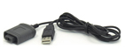
- USB-cable with galvanic isolation

| AM-1038 Professional Precision Digital Multimeter - front view |
|
|
| AM-1038 Professional Precision Digital Multimeter - side view |
|
|
| AM-1038 Professional Precision Digital Multimeter - top view |
|
|
|
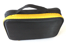
| AM-1038 Professional Precision Digital Multimeter - with accessories |
|
|
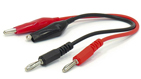
| AM-1038 Professional Precision Digital Multimeter - "crocodile" clips |
|
|
| AM-1038 Professional Precision Digital Multimeter - optical USB cable |
|
|
|
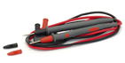
| AM-1038 Professional Precision Digital Multimeter - test leads |
|
|
DCmV / ACmV / DCmV+ACmV Measurement
The voltage measurement range is of 1μV…500mV and the measurement methods are as follows:
- Turn on the power switch and set the rotary switch to the position m
 . .
- Insert the red testing line into the VΩHz end and the black testing line into the COM end.
- Press the SELECT key to select DCmV or AcmV or DCmV+AcmV measurement modes.
- When performing DCmV measurement, connect the red probe to the positive polarity of the measured voltage and the black probe to its negative polarity. While performing ACmV or DCmV+ACmV measurement, it will be done by connecting the red probe and the black probe into the two ends of the measured voltage.
- Read the measured value from the display screen. If OL displaying on the meter, it indicates the measured voltage exceeding the range of the meter and it is necessary to remove both the red and black probes from the measured circuit immediately.
- When performing DCmV or ACmV measurement, by pressing the RANGE key it is possible to select range manually. The indicator of range indicates the range value. If OL displaying during manual range measurement, it is necessary to select a larger range. If OL displaying under the maximum range, it is necessary to remove both the red and black probes from the measured circuit immediately. When performing DCmV+ACmV measurement automatic range will be held and it is void to press the RANGE key.
Notes: In case of probe hanging in the air, the voltage inducted by the testing line may cause unstable readings on the display screen, but that will not affect the accuracy of measurement. When performing DCmV+ACmV measurement it will be relatively slow to refresh the measured data as it needs time to switch AC and DC measurements and to calculate RMS.
DCμA / ACμA / DCμA+ACμA Measurement
The measurement range of current is of AC or DC 0.01μA…5000μA , and the measurement methods are as follows:
- Turn on the power switch and set the rotary switch to the position

- Insert the red testing line into the mA/μA input end and the black testing line into the COM input end.
- Press the SELECT key to select the DcμA, AcμA or the DcμA+AcμA measurement modes.
- Turn off the power of the measured circuit, connect the red and black probes to the measured circuit in serial way and then turn on the power of the measured circuit.
- Read the measured value from the display screen. If it displays as positive during the DC measurement, it means the current is flowing into the meter from the red testing line, while it displaying as negative, it means the current is flowing into the meter from the black testing line. If it displays as OL, it means current exceeding range.
- During measurement of DCμA or ACμA, it is possible to select range manually by pressing the RANGE key. Under the DCμA+ACμA measurement mode, automatic range is held and it is null to press the RANGE key.
Notes: Under the DCμA+ACμA measurement mode, it is relatively slow to refresh the measured data as it is needs time to switch AC and DC measurements and to calculate RMS.
ACV/dBm Measurement
The range of voltage is of AC 0.5V…1000V and the measurement methods are as follows:
- Turn on the power switch and set the rotary switch to the position of
 . .
- Insert the red and black testing lines into VΩHz end and COM end respectively.
- Select the ACV or dBm measurement mode with the SELECT key.
- Connect the meter to the two ends of the measured voltage with the red and black probes.
- Read the meter’s data from the display screen. When OL displaying on the meter, it indicates the measured voltage exceeding the meter’s range and it is necessary to remove both the red and black probes from the measured circuit immediately.
- By pressing the RANGE key it is possible to select range manually. Indicator of range displays range. While displaying OL during manual range measurement, it is necessary to select a larger range. When OL displaying under the maximum range, it indicates the voltage exceeding 1000V, so it is necessary to remove both the red and black probes from the measured circuit immediately.
- To perform dBm measurement, press the RANGE key to select the resistance value needed for calculating dBm,there are 4, 8, 16, 32, 50, 75, 93, 110, 125, 135, 150, 200, 250, 300, 500, 600, 800, 900, 1000 and 1200 ohms being possible to be selected respectively.
Notes: in case of probe hanging in the air, the voltage inducted by the testing line may cause unstable readings on the display screen, but that will not affect the accuracy of measurement.
Capacitance Measurement
The measurement range of capacitance is of 10pF…5000μF and the measurement methods are as follows:
- Turn on the power switch and set the rotary switch to the position

- Insert the red and black testing lines into the VΩHz input end and the COM input end respectively.
- If exists voltage in the capacitor, connect the two ends of the capacitor for a short time to discharge.
- Connect the red and black probes to the two ends of the capacitor, if the measured capacitor is heteropolar, it is necessary to connect the red probe to the positive polarity of the capacitor and the black probe to its negative polarity.
- Read the capacitance from the display screen. If capacitance value >5300μF, the meter will display OL, while capacitance value <10pF,it will display zero.
- It is possible to select range manually by pressing the RANGE key. The indicator of range indicates the value of range. If OL displaying during manual range measurement, it is necessary to select a larger range.If it has been the largest range, which means capacitance value >5300μF.
Notes: When performing measurement on 500μF…5000μF capacitor, in order to ensure measurement accuracy the meter takes a relative long time to discharge capacitor, so it is relatively slow in refreshing the measured value. In addition,not to perform Capacitance measurement on a circuit board on which there are other parallel devices, for that may leads to very large error.
DC Ampere / AC Ampere / DC Ampere + AC Ampere Measurement
The measurement range of current is of AC or DC 0.1mA…10A and the measurement methods are as follows:
- Turn on the power switch and set the rotary switch to the position

- Insert the red testing line into the A input end and the black testing line into the COM input end.
- Press the SELECT key to select the DCA, ACA or DCA+ACA measurement modes.
- Turn off the power of the measured circuit, connect the red and black probes to the measured circuit in a serial way and then turn on the power of the measured circuit again.
- Read the measured value from the display screen. During the DC measurement, if it displays as positive, it means the current is flowing into the meter from the red testing line, while it displays as negative, it means the current is flowing into the meter from the black testing line. If it displays OL, it indicates current exceeding range.
- When performing DCA or ACA measurement, it is possible to select range manually by pressing the Range key. Under the DCA+ACA measurement mode, automatic range is held and it is null to press the RANGE key.
Notes: Under the DCA+ACA measurement mode, it is relatively slow to refresh the measured data as it is needs time to switch AC and DC measurements and to calculate RMS.
DCmA / ACmA / DCmA+ACmA Measurements
The measurement range of current is of AC or DC 1μA…500mA and the measurement methods are as follows:
- Turn on the power switch and set the rotary switch to the position

- Insert the red testing line into the mA/μA input end and the black testing line into the COM input end.
- Press the SELECT key to select the DCmA, ACmA or the DCmA+ACmA measurement modes.
- Turn off the power of the measured circuit, connect the red and black probes to the measured circuit in a serial way and then turn on the power of the measured circuit again.
- Read the measured value from the display screen. If it displays as positive during DC measurement, it means the current is flowing into the meter from the red testing line, while it displays as negative, it means the current is flowing into the meter from the black testing line. If it displays OL, indicating current exceeding range.
- When performing DCmA or ACmA measurement, it is possible to select range manually by pressing the RANGE key. Under the DCmA+ACmA measurement mode the automatic range is held and it is null to press the RANGE key.
Notes: Under the DCmA+ACmA measurement mode, it is relatively slow to refresh the measured data as it needs time to switch AC and DC measurements and to calculate RMS.
DCV / DCV+ACV Measurement
The range of voltage is of AC or DC 0.5V…1000V and the methods are as follows:
- Turn on the power switch and set the rotary-table switch to the position .
- Insert the red testing line into the VΩHz end and the black testing line into the COM end.
- Press SELECT key to select DCV or DCV + ACV measurement mode.
- When performing DCV measurement, connect the red probe to the positive polarity of the measured voltage and the black probe to the negative polarity of the measured voltage. While performing DCV + ACV measurement, it will be done by connecting the red probe and the black probe into the two ends of the measured voltage.
- Read the measured value from the display screen. If OL displaying on the meter, it indicates the measured voltage exceeding the range of the meter and it is necessary to remove the both red and black probes from the measured circuit immediately.
- When performing DCV measurement, by pressing the RANGE key it is possible to select range manually. The indicator of range indicates the range value. If OL displaying during manual range measurement, it is necessary to select a larger range. If OL displaying under the maximum range, it indicates the voltage exceeding 1000V and it is necessary to remove the both red and black probes from the measured circuit immediately. When performing DCV + ACV measurement automatic range will be held and it is null to press the RANGE key.
Notes: in case of probe hanging in the air, the voltage inducted by the testing line may cause unstable readings on the display screen, but that will not affect the accuracy of measurement. When performing DCV + ACV measurement it will be relatively slow to refresh the measured data as it needs time to switch AC and DC measurements and to calculate RMS.
Diode Measurement
The measurement range of diode is of 0…2.5V. The measurement methods are as follows:
- Turn on the power switch and set the rotary switch to the position

- Insert the red testing line into the VΩHz end and the black testing line into the COM end.
- Connect the red probe to the positive polarity of the diode and the black probe to its negative polarity, while the display screen will display the forward voltage drop.
- Connect the black probe to the positive polarity of the diode and the red probe to its negative polarity, if OL displaying on the display screen, it indicates the backward resistance of the diode being normal, while OL not displaying, it indicates that the diode is backward leaking.
Linear Frequency Measurement
The measurement range is of 5Hz…200kHz and the measurement methods are as follows:
- When performing voltage or current measurement, in case of measured value being AC or including AC elements, it is possible to measure and display the alternating frequency by pressing the Hz key. However it has a certain requirements for the amplitude of alternating signal and the meter has varied requirements for signal amplitude when it is in different ranges, for information of which please refer to Table.
- If the position of rotary switch is in ACV or DCV, after pressing Hz key the indicator of range will indicates the meter’s present voltage range. In addition, it is possible to change the range by pressing the RANGE key to meet the different voltages.
- Press Hz key again to exit linear frequency
| Range | Sensibility (sine wave) |
|---|
| 500mV | 100mV |
| 5V | 0.5V |
| 50V | 4V |
| 500V | 40V |
| 1000V | 400V |
| 5000μA | 1mA |
| 500mA | 500mA |
Notes: During ampere measurement, due to the very small sample resistor, and the very weak frequency signal produced, so only when current reaching as large as over 5A can the frequency be measured.
Logic Frequency / Duty Ratio Measurement
The frequency range is of 5Hz…2MHz (Vp 2.5…5V), while the duty ratio measurement range being of 5%…95%. And the measurement methods are as follows:
- Turn on the power switch and set the rotary switch to the position Hz%
- Insert the red testing line into the VΩHz end and the black testing line into the COM end.
- Press the SELECT key to select the logic frequency (Hz) or duty ratio (%) modes.
- Connect the red testing line to high logic level, the black one to low logic level.
- Read the measured value from the display screen. If the frequency of the measured signal is lower or higher than the meter’s measurement range, the reading will be displayed as zero. If the amplitude of signal is too low or the low level is larger than 1 volt, the reading will also displayed as zero.
- This measurement is of automatic range, it is null to press the RANGE key.
Resistance / Continuity Test
The measurement range of resistance is of 0.01Ω…50MΩ and the measurement methods are as follows:
- Turn on the power switch and set the rotary switch to the position Ω

- Insert the red and black testing lines into the VΩH input end and the COM input end respectively.
- Press the SELECT key to select resistance (Ω) or the continuity () modes.
- For the resistance measurement, connect the red and black probes to the two ends of resistor and read the resistance value from the display screen. If OL displaying, it indicates the resistor is larger than 50MΩ. As for the continuity measurement, connect the red and black probes to the two measured points respectively. In case of the resistance between the two points being less than about 50Ω…60Ω, the buzzer will sound while the display screen displaying the value of resistance. If OL displaying, it indicates the resistance between the two points is larger than 500Ω.
- When the resistance measurement mode being implemented, it is possible to select range by pressing the RANGE key. The indicator of range indicates the value of range. If OL displaying during manual range measurement, it is necessary to select a larger range. Under the continuity measurement mode it is null to press the RANGE key.
Notes: In case of performing resistance or continuity test on circuit board, it is necessary firstly to turn off the power of the circuit board and then perform the measurement. As there may be other parallel circuits, so the displayed value of test is not surely the actual value of the resistor.
Frequently Asked Questions
There are problems when connecting AKTAKOM AM-1038 multimeter, what should be done?
Is it possible to operate several software copies of AM-1038 set simultaneously and independently on one PC?
Does AKTAKOM AM-1038 multimeter have auto power off function?
Can I deactivate Auto Power Off function of AKTAKOM AM-1038 multimeter?
| There are problems when connecting AKTAKOM AM-1038 multimeter, what should be done? |
|
There can be several reasons and solutions accordingly:
- Installation failure / wrong installation of the software
Reinstall the program and the driver, restart the PC and reset the software once again;
- Error has been caused by the operation system
Try connecting the device to another PC, if it operates properly the problem is connected with your PC, if you see the same error the device requires service repair.
- Wrong driver on the CD (the CD contains wrong optical cable driver)
Download and install free USB to Serial Bridge Prolific PL-2303 converter driver. Afterwards optical cable from AM-1038 set should be successfully detected by the OS when connecting to USB.
Up
|
| Is it possible to operate several software copies of AM-1038 set simultaneously and independently on one PC? |
|
Yes, it’s possible!
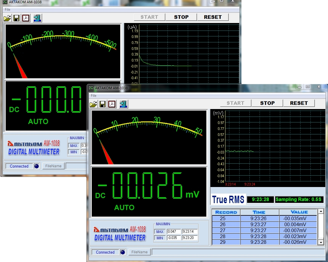
AM-1038 software recognizes the device connection port automatically. If you connect several devices to different USB-ports of one PC (activating PC-Link mode on each of them by keeping HOLD button pressed), run a respective number of the Software copies and press START button one by one in each Software you will see an independent data collection of the appropriate device.
The below screenshot demonstrates the example of simultaneous operation of 2 devices (one of them is in “µA” mode, the other one – in “mV” mode)
Up
|
| Does AKTAKOM AM-1038 multimeter have auto power off function? |
|
Yes, it does. There is Auto Power Off function in AM-1038: the device power automatically goes off if you do not use the device within 15 minutes. To start the operation again after Auto Power Off you need to press WAKE button or turn the rotary switch.
Up
|
| Can I deactivate Auto Power Off function of AKTAKOM AM-1038 multimeter? |
To deactivate Auto Power Off function of AM-1038 you need to keep WAKE button pressed when you power on the multimeter.
Up
|
Precision Digital Multimeter AKTAKOM AM-1038
Back to the section
|
|


