DC mV/AC mV Measurement
The testing chart is shown in the Figure. The voltage measurement range is of 10μV…220mV and the measurement methods are as follows:
- Turn on the power switch and set the rotary switch to the position
 .
.
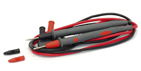
- Insert the red testing line into the VΩHz end and the black testing line into the COM end.
- Press the FUNC. key to select DCmV measurement modes.
- When performing DCmV or AcmV measurement, connect the red probe to the positive polarity of the measured voltage and the black probe to its negative polarity.
- Read the measured value from the display screen. If OL displaying on the meter, it indicates the measured voltage exceeding the range of the meter and it is necessary to remove both the red and black probes from the measured circuit immediately.
- In this mode, it is null to press the RANGE key
Notes:
- In case of probe hanging in the air, the voltage inducted by the testing line may cause unstable readings on the display screen, but that will not affect the accuracy of measurement.
- The meter is a true rms responding meter. When the input leads are shorted together in the ac functions, the Meter may display a residual reading between 1 and 30 counts. It will not attect stated accuracy, but if using REL to offset this reading may produce a much larger constant error in later measurements.
DC/AC μA Measurement
The measurement is seen in Figure, the measurement range of current is of AC or DC 0.01μA…2200μA, and the measurement methods are as follows:
- Turn on the power switch and set the rotary switch to the position
 .
.
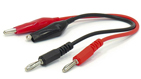
- Insert the red testing line into the mA/μA input end and the black testing line into the COM input end.
- Press the FUNC. key to select the DC μA or AC μA measurement modes.
- Turn off the power of the measured circuit, connect the red and black probes to the measured circuit in serial way and then turn on the power of the measured circuit.
- Read the measured value from the display screen. If it displays as positive during the DC measurement, it means the current is flowing into the meter from the red testing line, while it displaying as negative, it means the current is flowing into the meter from the black testing line. If it displays as OL, it means current exceeding range.
- During measurement of DC μA or AC μA, it is possible to select range manually by pressing the RANGE key.
Notes: In this mode the Meter may display a initial reading between 1 and 5 counts when no signal input, but that will not affect the accuracy of measurement. Using REL to offset this reading may produce a much larger constant error in later measurements.
Backlight Control
Pressing the LIGHT key, the LCD display screens backlight will be lighted and after 60 seconds it will automatically go out. If press the LIGHT key again when the backlight is lighting, the backlight can be turned off in advance. Lighting the backlight will cause three-time higher energy consumption than the ordinary operation. So by less use of backlight, power can be saved.
Maximum Value/Minimum Value Measurement
Except for frequency and diode measurements, by pressing the MAX/MIN key the meter will enter the maximum value and minimum value record state and display the maximum value. The meter measures the present value and continuously judges if it is necessary to update the maximum or minimum value. Pressing the MAX/MIN key again it is possible to select displaying the minimum value, the current value or the maximum value. When the meter being in the maximum and the minimum value record state, the analog bar is always indicating the present measurement value but not the MAX/MIN value. Under the maximum and minimum value record state, press the MAX/MIN key for two seconds and then release it, the meter will exit the MAX/MIN record state. When measurement over, OL will display instead of showing the MAX/MIN value.
PEAK max/min Measurement
When you measurement AC signal, by pressing the PEAK key less than 1second the meter will enter the Peak maximum value after it be calibration. Pressing the PEAK key again (less than 1s) it will enter the Peak minimum value. By pressing the PEAK key for more than 1 seconds and release it, the meter will exit the PEAK max/min record state. When measurement over, OL will display instead of showing the PEAK max/min value.
Relative Value Measurement
Except for frequency/duty ratio and diode measurements, all other measurements can employ relative measurement. Press REL key to enter relative measurement and the meter will record the initial value when pressing the key. And the later displayed value is:
Displayed value = present measurement value —Initial value
Press REL again to exit relative measurement. Changes of measurement value may be found in relative measurement which also can be used for the small resistance and the small capacitance measurements, for example, when performing resistance measurement, connect the red testing line and the black testing line in short, press the REL key to record the values of resistance (resistance of both the red and black lines), and after that performing resistance measurement again the lead resistance will have been taken off from the displayed value. When performing capacitance measurement, open the red and black testing line, press REL key to record the distributed capacitance, and after that performing capacitance measurement again, the distributed capacitance will have been taken off from the displayed value. During relative measurement, analog bar is always indicating the present measurement value but not the relative value. When measurement over, OL will display instead of showing the relative value.
ACV Measurement
The measurement is shown as in Figure, with voltage range being of AC 0.23V…1000V and the measurement methods being as follows:
- Turn on the power switch and set the rotary switch to the position of
 .
.
- Insert the red and black testing lines into VΩHz end and COM end respectively.
- Press FUNC. key to select ACV measurement mode.
- Connect the meter to the two ends of the measured voltage with the red and black probes.
- Read the meter’s data from the display screen. When OL displaying on the meter, it indicates the measured voltage exceeding the meter’s range and it is necessary to remove both the red and black probes from the measured circuit immediately.
- By pressing the RANGE key it is possible to select range manually. Indicator of range displays range. While displaying OL during manual range measurement, it is necessary to select a larger range. When OL displaying under the maximum range, it indicates the voltage exceeding 1000V, so it is necessary to remove both the red and black probes from the measured circuit immediately.
Notes: in case of probe hanging in the air, the voltage inducted by the testing line may cause unstable readings on the display screen, but that will not affect the accuracy of measurement.
 Warning! Not try to measure a voltage higher than 1000V
Capacitance Measurement
The measurement chart is seen in Figure. The measurement range of capacitance is of 10pF…220mF and the measurement methods are as follows:
- Turn on the power switch and set the rotary switch to the position
 .
.
- Insert the red and black testing lines into the VΩHz input end and the COM input end respectively.
- If exists voltage in the capacitor, connect the two ends of the capacitor for a short time to discharge.
- Connect the red and black probes to the two ends of the capacitor, if the measured capacitor is heteropolar, it is necessary to connect the red probe to the positive polarity of the capacitor and the black probe to its negative polarity.
- Read the capacitance from the display screen. If capacitance value >220mF, the meter will display OL, while capacitance value <10pF, it will display zero.
- It is possible to select range manually by pressing the RANGE key. The indicator of range indicates the value of range. If OL displaying during manual range measurement, it is necessary to select a larger range. If it has been the largest range, which means capacitance value >220mF.
Notes: When performing measurement on 10mF capacitor, in order to ensure measurement accuracy the meter takes a relative long time to discharge capacitor, so it is relatively slow in refreshing the measured value. In addition, not to perform Capacitance measurement on a circuit board on which there are other parallel devices, for that may leads to very large error.
DC/AC A Measurement
The measurement is seen in Figure, the measurement range of current is of AC or DC 1mA…10A and the measurement methods are as follows:
- Turn on the power switch and set the rotary switch to the position
 .
.
- Insert the red testing line into the A input end and the black testing line into the COM input end.
- Press the FUNC. key to select the DC A or AC A measurement modes.
- Turn off the power of the measured circuit, connect the red and black probes to the measured circuit in a serial way and then turn on the power of the measured circuit again.
- Read the measured value from the display screen. During the DC measurement, if it displays as positive, it means the current is flowing into the meter from the red testing line, while it displays as negative, it means the current is flowing into the meter from the black testing line. If it displays OL, it indicates current exceeding range.
- When performing DC A or AC A measurement, it is null to press the RANGE key.
DC/AC mA Measurements
The measurement is seen in the Figure. The measurement range of current is of AC or DC 1μA…220mA and the measurement methods are as follows:
- Turn on the power switch and set the rotary switch to the position
 .
.
- Insert the red testing line into the mA/μA input end and the black testing line into the COM input end.
- Press the FUNC. key to select the DC mA or AC mA measurement modes.
- Turn off the power of the measured circuit, connect the red and black probes to the measured circuit in a serial way and then turn on the power of the measured circuit again.
- Read the measured value from the display screen. If it displays as positive during DC measurement, it means the current is flowing into the meter from the red testing line, while it displays as negative, it means the current is flowing into the meter from the black testing line. If it displays OL, indicating current exceeding range.
- When performing DC mA or AC mA measurement, it is possible to select range manually by pressing the RANGE key.
Notes: In this mode the Meter may display a initial reading between 1 and 5 counts when no signal input, but that will not affect the accuracy of measurement. Using REL to offset this reading may produce a much larger constant error in later measurements.
DCV Measurement
The range of voltage is of DC 0.23…1000V and the methods are as follows:
- Switch and set the rotary-table switch to the position .
- Insert the red testing line into the VΩ°C end and the black testing line into the COM end.
- When performing DCV measurement, connect the red probe to the positive polarity of the measured voltage and the black probe to the negative polarity of the measured voltage.
- Read the measured value from the display screen. If OL displaying on the meter, it indicates the measured voltage exceeding the range of the meter and it is necessary to remove the both red and black probes from the measured circuit immediately.
- When performing DCV measurement, by pressing the RANGE key it is possible to select range manually. If OL displaying during manual range measurement, it is necessary to select a larger range. If OL displaying under the maximum range, it indicates the voltage exceeding 1000V and it is necessary to remove the both red and black probes from the measured circuit immediately.
Notes: in case of probe hanging in the air, the voltage inducted by the testing line may cause unstable readings on the display screen, but that will not affect the accuracy of measurement.
Warning! Not try to measure a voltage higher than 1000V
Linear Frequency Measurement
The measurement range is of 5Hz…200kHz and the measurement methods are as follows:
- When performing voltage or current measurement, in case of measured value being AC or including AC elements, it is possible to measure and display the alternating frequency by pressing the Hz/DUTY key. However it has a certain requirements for the amplitude of alternating signal and the meter has varied requirements for signal amplitude when it is in different ranges, for information of which please refer to Table.
- If the position of rotary switch is in ACV or DCV, after pressing Hz/DUTY key the RANGE key will invalidation.
- Press Hz/DUTY key again to enter DUTY measurement mode.
- Press Hz/DUTY key again to exit linear frequency.
| Range | Sensibility (sine wave) |
|---|
| 220mV | 100mV |
| 2.2V | 0.5V |
| 22V | 4V |
| 220V | 40V |
| 1000V | 400V |
Logic Frequency/Duty Ratio Measurement
The testing chart is shown in the Figure. The frequency range is of 2.01Hz…10MHz (Vp 0.35…5V), while the duty ratio measurement range being of 5%…94.9%. And the measurement methods are as follows:
- Turn on the power switch and set the rotary switch to the position
 .
.
- Insert the red testing line into the VΩHz end and the black testing line into the COM end.
- Press the HZ/DUTY key to select the duty ratio (%) modes.
- Connect the red testing line to high logic level, the black one to low logic level.
- Read the measured value from the display screen. If the frequency of the measured signal is lower than 2.01Hz, the reading will be displayed as zero. If the amplitude of signal is too low or the low level is larger than 0.35V, the reading will also displayed as zero.
- If the frequency of the duty ratio is lower than 5%, the reading will be displayed as UL. If the duty ratio is bigger than 95% the reading will also displayed as OL.
- This measurement is of automatic range or manual range, it is available to press the RANGE key
Resistance/continuity Test/Diode Measurement
The test chart is seen in Figure. The measurement range of resistance is of 0.01Ω…220MΩ and the measurement methods are as follows:
- Turn on the power switch and set the rotary switch to the position
 Ω
Ω .
.
- Insert the red and black testing lines into the VΩH input end and the COM input end respectively.
- Press the FUNC, key to select resistance (Ω), the continuity ()or the diode measurement () modes
- For the Resistance measurement, connect the red and black probes to the two ends of resistor and read the resistance value from the display screen. If OL displaying, it indicates the resistor is larger than 220MΩ. As for the Continuity measurement, connect the red and black probes to the two measured points respectively. In case of the resistance between the two points being less than about 30Ω, the buzzer will sound while the display screen displaying the value of resistance. As for the Diode measurement, connect the red and black probes to the positive and negative polarity. while the display screen will display the forward voltage drop. If the forward voltage drop is larger than 2V the OL will be displayed. When the resistance measurement mode being implemented, it is possible to select range by pressing the RANGE key. The indicator of range indicates the value of range. If OL displaying during manual range measurement, it is necessary to select a larger range. Under the continuity measurement mode it is null to press the RANGE key.
Notes: In case of performing resistance, continuity or diode test on circuit board, it is necessary firstly to turn off the power of the circuit board and then perform the measurement. As there may be other parallel circuits, so the displayed value of test is not surely the actual value of the resistor.
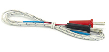
Temperature Measurement
- Turn on the power switch and set the rotary switch to the position °C.
- The 'LCD' display will show the approx. current environment temperature.
- Press the FUNC. key to select the °C or °F measurement modes.
- When measuring the temperature with thermocouple, 'K' type probe for this meter can be used. Insert the black plug to the COM jack and the red one to the °C jack, touch the end of the temperature sensor to the area or surface of the object for measurement.
- You can get reading from LCD.