|
|||||
|
|
||||
|
|||||
|
|
||||
|
Search
Log in
|
AKTAKOM Power Manager 21 Professional (APM21 Pro)
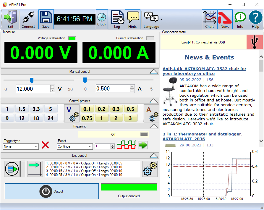
AKTAKOM Power Manager 21 Professional software is designed to remotely control compatible AKTAKOM APS-XXXX power supplies with USB or LAN interface. Program descriptionUser interface
Buttons on the top bar of the main window: The "Exit" button exits the program. The "Connection" button calls up the dialog for connecting to a power source. The "Save" button allows you to save the data displayed on the chart to a file. A button with a clock icon shows or hides the display of the clock on the keypad. The "Protocol" button opens the program operation history window. The Tips button shows or hides the display of button labels. The "Language" menu is used to select the language of the program interface. The Graph button shows or hides the measurement graph. The "News" button shows or hides the Aktakom news feed. The "About" button displays a dialog with information about the program and the connected device. The "Help" button calls this help file. Block "Connection status". Shows the current status of connection to the power supply. Block "Measurements". Contains indicators with the results of measurements of current parameters at the output of the device. Block "Manual control". Allows manual control of the main current parameters. Block "Control Templates". Allows you to control current parameters using predefined presets. Synchronization block. Used to work with the synchronization system (only for models with index S). Block "Control list". Allows you to control the current parameters automatically using a predefined list of commands. Note: control and synchronization blocks can be hidden or shown at the user's choice. The "Output" button turns the current output of the power supply on or off. Connecting to the deviceWhen you first start the application, the power supply connection dialog will immediately open: Select the desired interface type (USB or LAN), enter the settings for the network connection (IP, port, login...) and press the OK button to connect to the power supply. If the program successfully detects the device and reads its serial number, it will ask you for a license key to work with it. Find the key combination that you received when you purchased the program or device, enter it in the dialog and click OK: You will see the connection result in the main program window, in the "Connection status" block. If the connection is successful, the program will remember the settings and the next time you start it, it will try to use them to automatically reconnect to the device. To reset the saved connection settings and return to the factory settings, click the "Reset LAN Settings" button. To restore the connection after a break while the program is running, click the "Connect" button in the main window. Also use this dialog to write the network settings to the power supply memory. To do this, after connecting to the device via USB, open the "Connection" dialog, enter the necessary settings in the IP, port, login fields and click the "Write LAN settings to power source" button. When recording, you will be asked to enter a password (default password: AULNetPass). The view of the password entry dialog is shown in the figure: To change the password, check the box "Change password with a new one" and enter a new password in the field below. If the USB interface is used and more than one power source is connected to the computer, a dialog will appear for selecting the required device from the list: Manual controlAfter connecting to the device, its current state will be displayed in the Measurements section of the main program window. The stabilization voltage and current are controlled by the elements of the Control block. Turning the output on and off is done with the Exit button. The Synchronization block allows you to use the capabilities of the synchronization input for instrument models equipped with it. Launch type:
Restart:
Counter:
Synchronization status indicator:
Comment.
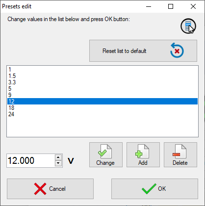
The on/off button for the outputs takes precedence over the timing settings. If the output is enabled (the button is pressed), synchronization will control the state of the outputs, but if it is disabled (the button is released, disabled), the outputs will always be disabled, regardless of the state of synchronization. AKTAKOM Power Manager 21 Professional software offers some advanced features, such as control templates, command lists, customizable user interface, history of events. Control templatesYou can use preconfigured templates (presets) to quickly set up the power supply. Templates are lists of commonly used voltage and current values. Customize the lists according to your preferences and set the desired current parameters at the touch of a button (main window of the program, block "Control templates").
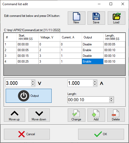
Command listsTo send a series of scheduled commands to the power supply, use the "List of commands" feature. Specify a sequence of commands consisting of specified values of voltage, current, output state and stage duration, save the resulting list to a file for further use and run it from the main program window ("Control List" block).
Customizable user interfaceAPM21 Pro allows to customize the user interface in a way that is convenient for you: hide and collapse all the blocks you dont need with special buttons and leave only the ones you need. History of eventsAPM21 Pro saves the history of events (displayed in the Protocol window) and measurement data (displayed on the graph in the main window) to a file. It is useful when you need to review power supply operation later. Computer requirementsThe computer used to operate the instrument must meet the following minimum requirements:
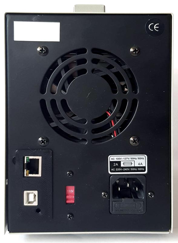
Preparing the device for workHardware installationTo prepare for installation on the device, turn it off, connect the USB connector of the computer port to the corresponding connector of the controlled power supply using the A-B type USB cable.
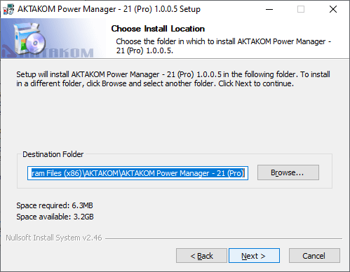
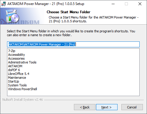
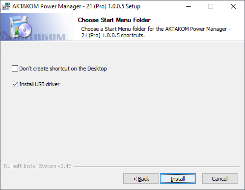
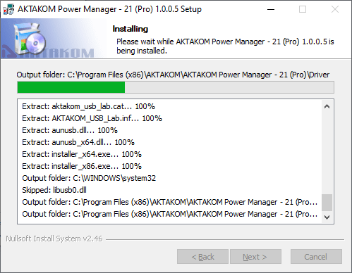
Software installationFind and run the installer and follow its instructions. At the end of the installation process, a program group will be created with shortcuts to the program and to the help system. You can launch them using the start menu. The USB interface driver must be installed before using the instrument. The files required for this will be placed in the working folder of the program in the Driver subfolder during the installation of the software, after which the installer will offer to install the driver automatically.
If you chose not to install the driver automatically, or if it failed for some reason, you can install the driver manually later. The driver installation procedure is described below. Manual installation of the USB driver (for Windows 7)Log in to Windows with administrator rights, connect the instrument to the computer. Call the Control Panel from the Start menu, select the System item (or just press the Win + Pause key combination on the keyboard). Click Device Manager. Find the AKTAKOM USB LAB device in it (it will be marked with a warning icon, since the driver for it has not yet been installed). Open its properties (double-click), click the Update driver button. Select "Search this computer for drivers" and then specify the location of the driver folder. Choose to install the AKTAKOM USB Lab driver. On the security warning, confirm your consent to install the driver. Wait for the installation to finish. At this point, the driver is ready to go. Standard packageThe software in the standard package of the device has no physical media (CD) and can be downloaded at www.tmatlantic.com after the purchasing and registering the equipment with a serial number. We recommend you save a copy of your software. If lost: registered user can download software free of charge during warranty period. After warranty period has expired the software could be purchased and downloaded from the TM Atlantic website. The software could be written on the CD and shipped to the customer for an additional fee and only upon request. Frequently Asked Questions
ALL RIGHTS RESERVED. AKTAKOM software is protected under International and Federal Copyright Laws and Treaties. Any unauthorized copy, reprint or use of this material is prohibited. No part of this software may be reproduced or transmitted in any form or by any means, electronic or mechanical, including photocopying, recording, or by any information storage and retrieval system without express written permission from the author / publisher. Windows, Windows logo are either registered trademarks or trademarks of Microsoft Corporation in the United States and/or other countries. Back to the section |

")