Search
Log in
Login:
Password:
Register
Forgot your password?

APS-3605 DC Power Supply

Single channel DC power supply with current limit. Rated Output Voltage: 0~60V (Adjustable). Rated Output Current: 0~5A (Adjustable). Rated Output Power: 600W. Large Digital Display with LED meter displays Volts & Amps 10mV (Voltage) / 10mA (Current). Ripple And Noise: ≤3mVrms. SMD technology. Dimensions (WxHxD): 10.4x5.5x14.2in/262x140x360mm. Weight: 24lb/10kg

Manuals: 
User's Manual (485.93 Kb)

AKTAKOM APS-3605 Single Output DC Regulated Bench power supply with Adjustable Current limit. Large Digital Display with LED meter displays Volts & Amps. Push button switch allows connection & removal of load. Multiturn Voltage control for precise settings. 3mV RMS ripple. Front panel output Banana Jacks & Terminal strip for remote Voltmeter Sensing at the load.

Features

  • SMD technology
  • Attractive digital display shows voltage and current
  • Cooling fan
  • High precision voltage regulation
  • Proqressive current regulation
  • Dual terminal system: Safety test style or expandable screw terminals
  • Overtoad protection circuit
  • Output polarity: positive or negative
  • Rugged reinforced metal frame construction

Specifications

  • Regulated Single Channel with Current Limit
  • Input: 110VAC 60Hz
  • Output: 0-60VDC @ 0-5A
  • Rated Output Power: 300W
  • Digital display shows voltage and current with LEDs
  • Display resolution: 10mV (Voltage) / 10mA (Current)
  • Ripple And Noise: ≤3mVrms
  • Dimensions (WxHxD): 10.4x5.5x14.2in / 262x140x360mm
  • Weight: 24lb / 10kg

Accessories

  • Pair of high power Cables with connectors

  • Power Cord

User Manual

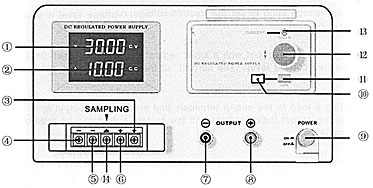
Operation instructions

  1. Press the power on/off button to turn power on.
  2. Adjust the voltage knob to set the desired voltage. (Voltage level is shown on the digital display).
  3. Adjust the current level pot with a small regular screwdriver to set the (maximum) desired current level. (The current of the power supply is set to be the maximum at the factory).
  4. Connecting a load to the output terminals and pressing the output switch will illuminate the output indicator light and the current output can be read on the digital display.
1. Voltage indication
2. Current indication
3. +S output port
4. -S output port
5. -Output port
6. +Output port
7. -Output terminal
8. +Output terminal
9. Power switch
10. Output light
11. Output switch
12. Voltage adjustment knob
13. Current adjustment pot
14. Chassis ground

Power supply to load four-wire connection method

The sampling terminals are used under the following conditions: if the load has a distance from the power supply, the sampling terminals may be used to compensate for the inherent when using voltage drop a longer power line.

Sampling terminals connection to compensate the voltage drop:

Voltage drop compensation

Sampling connection diagram:

Attention: Disconnect the installed S- and S+ shorting wires when using the sampling connections.

Frequently Asked Questions

  • How can I work in the current stabilization mode?
  • What instruction should I follow to work in the voltage stabilization mode?
  • May I use AKTAKOM power supplies to charge accumulators?

  • How can I work in the current stabilization mode?
    1. If OUTPUT indicator is red than press LOAD button. In that case OUTPUT indicator should go out and the current indicator will display the set current value.
    2. By using VOLTAGE adjustment rotary switch set the required output voltage (at the same time nothing should be connected to the output terminals «+» and «-»).
    3. By using CURRENT rotary switch set the maximum allowable current value (current limit value) for your load. If in the operating mode the load resistance change will cause the excess of the specified current limit, the device will automatically switch to the current stabilization mode and the output voltage will proportionally fall.
    4. Connect the load to the device and press LOAD button. OUTPUT indicator should become red.
    5. Before you disconnect the load press LOAD button. OUTPUT indicator will go out.
    6. Before switching off the device, disconnect the load.


    Up

    What instruction should I follow to work in the voltage stabilization mode?
    1. If OUTPUT indicator is red than press LOAD button. In that case OUTPUT indicator should go out and the current indicator will display the set current value.
    2. Adjust VOLTAGE adjustment rotary switches in order to obtain the maximum allowable load voltage on the device output. If in the operating mode the load resistance change will cause the excess of the specified voltage limit, the device will automatically switch to the voltage stabilization mode with setting on terminals «+» and «-» of the preset voltage value limit, and the output current will proportionally fall.
    3. By using CURRENT rotary switch set the maximum allowable current value (current limit value) for your load.
    4. Connect the load to the device and press LOAD button. OUTPUT indicator should become red.
    5. Before you disconnect the load press LOAD button. OUTPUT indicator will go out.
    6. Before switching off the device, disconnect the load.


    Up

    May I use AKTAKOM power supplies to charge accumulators?

    AKTAKOM power supplies can’t be used for accumulator charging since it may cause the accumulator breakage (recharge, electrolyte boiling, extra pressure of the internal gas which will lead to the accumulator explosion). Accumulators should be charged with the current source which controls the accumulator voltage and regulates the charging current accordingly. When the required accumulator voltage is achieved such type of source simply stops the charging process, its name is a charging device.


    Up


    Back to the section