The sound level function can be used to measure noise in factories, schools, offices, home, etc, checking acoustics of studios, auditoriums and hi-fi installations. The light function is used to measure luminance in the field. It is fully cosine corrected for the angular incidence of light. The light sensitive component used in the meter is a very stable, long life silicon ciode. The humidity/temperature uses a humidity /semiconductor sensor and K type thermocouple. The DMM function includes ACV, DCV, ACA, DCA, resistance, capacitance, frequency, duty cycle, diode, continuity test and Non-contact AC voltage detector.
6 in 1 Digital Multimeter AKTAKOM AMM-1062 with Environment Measurement has been designed to combine the functions of Sound Level Meter, Light Meter, Humidity Meter, Temperature Meter& Non-contact AC voltage detector. They are ideal multifunction environment & DMM instruments with scores of practical applications for professional and home use.
Features
The sound level function can be used to measure noise in factories, schools, offices, home, etc, checking acoustics of studios, auditoriums and hi-fi installations.
The light function is used to measure luminance in the field. It is fully cosine corrected for the angular incidence of light. The light sensitive component used in the meter is a very stable, long life silicon ciode. The humidity/temperature uses a humidity /semiconductor sensor and K type thermocouple.
The DMM function include ACV, DCV, ACA, DCA, resistance, capacitance, frequency, duty cycle, diode, continuity test and Non-contact AC voltage detector.
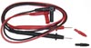
Insert the black lead banana plug into the negative COM jack.
Insert the red test lead banana plug into the "V/Hz%/Ω/Cap/°C" jack.
Press the MODE button to indicate "" and "Ω" on the display
Touch the test probe tips to the circuit or wire you wish to check.
If the resistance is less than approximately 50Ω, the audible signal will sound. If the circuit is open, the display will indicate "OL".
Measuring AC Current
Insert the black test lead banana plug into the negative COM jack and the red test lead banana plug into the "μA/mA" or "10A" jack
For current measurements up to 4000uA AC, set the function switch to the uA position and insert the red test lead banana plug into the μA/mA jack
For current measurements up to 400mA AC, set the function switch to the mA position and insert the red test lead banana plug into the μA/mA jack
For current measurements up to 10A AC, set the function switch to the yellow 10A position and insert the red test lead banana plug into the 10A jack
Press the MODE button to indicate "AC" on the display
Remove power from the circuit under test then open up the circuit at the point where you wish to measure current
Touch the black test probe tip to the neutral side of the circuit. Touch the red test probe tip to the "hot" side of the circuit
Apply power to the circuit
Read the current in the display
Press and hold the Hz% button to indicate "Hz"
Read the frequency in the display
Momentarily press the Hz% button again to indicate "%"
Read the % duty cycle in the display
Press and hold the Hz% button to return to current measurement.
Measuring AC Voltage
Insert the black test lead banana to the COM jack and red test lead banana to the "V/Hz%/Ω/Cap/°C" jack
Set the function switch to the green at AC ranges to be used and connect test leads across the source or load under measurement
Read LCD display. The polarity of red connection will be indicated when making a AC measurement
Press the Hz% button to indicate "Hz"
Read the frequency in the display
Press the Hz% button again to indicate "%"
Read the % of duty cycle in the display.
Measuring Capacitance
Set the function switch to the green CAP position
Insert the black test lead banana plug into the negative COM jack and the red test lead banana plug into the “V/Hz%/Ω/Cap/°C” jack (If value is not zero in the display press REL button to zero)
Touch the test probe tips across the part under test
Read the capacitance value in the display
The display will indicate the proper decimal point and value.
Measuring DC Current
Insert the black test lead banana plug into the negative COM jack and the red test lead banana plug into the "μA/mA" or "10A" jack
For current measurements up to 4000μA DC, set the function switch to the μA position and insert the red test lead banana plug into the μA/mA jack
For current measurements up to 400mA DC, set the function switch to the mA position and insert the red test lead banana plug into the μA/mA jack
For current measurements up to 10A DC, set the function switch to the yellow 10A position and insert the red test lead banana plug into the 10A jack
Press the MODE button to indicate "DC" on the display
Remove power from the circuit under test, then open up the circuit at the point where you wish to measure current
Touch the black test probe tip to the negative side of the circuit. Touch the red test probe tip to the positive side of the circuit
Apply power to the circuit
Read the current in the display.
Measuring DC Voltage
Insert the black test lead banana to the COM jack and red test lead banana to the "V/Hz%/Ω/Cap/°C" jack
Set the function switch to the green at DCV ranges to be used and connect test leads across the source or load under measurement
Set the function switch at DCmV ranges to be used, connect test leads across the source or load under measurement
Read LCD display. The polarity of red connection will be indicated when making a DC measurement
Press the Hz% button to indicate "Hz"
Read the frequency in the display
Press the Hz% button again to indicate "%"
Read the % of duty cycle in the display.
Diode Test
Set the function switch to the green Ω position.
Insert the black test lead banana plug into the negative COM jack and the red test lead banana plug into the "V/Hz%/Ω/Cap/°C" jack.
Press the MODE button to indicate "" and "V" on the display.
Touch the test probes to the diode under test. Forward voltage will typically indicate 0.400 to 0.700V. Reverse voltage will indicate "OL". Shorted devices will indicate near 0V and an open device will indicate "OL" in both polarities.
Measuring Frequency
Set the function switch to the Hz position.
Insert the black test lead banana plug into the negative (COM) jack
Insert the red test lead banana plug into the V/Hz%/Ω/Cap/°C jack.
Touch the test probe tips to the circuit under test.
Read the frequency in the display.
The digital reading will indicate the proper decimal point, symbols (Hz, kHz, MHz) and value.
Measuring Humidity
Humidity Measurement for indoor:
Set the function switch to the ON position.
Remove the meter place to the room.
Read the %RH in the display for about two hours.
Measuring Light
Set the function switch to the green "lux" scale and set the range to desired ("lux" or "x10 lux") range.
Remove the meter and face the photo detector to light source in a horizontal position.
Read the illuminance nominal from the LCD display.
Over-range: If the instrument only display one "1" in the M.S.D. the input signal is too strong, and a higher range should be selected.
When the measurement is completed. Replace the photo detector from the light source.
Spectral sensitivity characteristic: To the detector, the applied photo diode with filters makes the spectral sensitivity characteristic almost meet C.I.E. (International Commission on Illumination) photopia curve V (λ) as the following chart described.
Recommended Illumination:
Locations
Lux
Office
Conference, Reception room.
Clerical work
Typewriting
200~750
700~1,500
1000~2,000
Factory
Packing, Entrance passage
Assembling line
Inspection work
Electronic parts assembly line
150~300
300~750
750~1,500
1,500~3,000
Hotel
Public, Cloakroom
Reception, Cashier
100~200
200~1,000
Store
Indoors Stairs, Corridor
Show window, Packing table
Forefront of show window
150~200
750~1,500
1,500~3,000
Hospital
Sickroom, Warehouse
Medical Examination room
Operating room, Emergency room
100~200
300~750
750~1,500
School
Auditorium, Indoor Gymnasium
Class room
Laboratory, Library, Drafting room
100~300
200~750
500~1,500
Measuring Resistance
Set the function switch to the green Ω position.
Insert the black test lead banana plug into the negative COM jack.
Insert the red test lead banana plug into the V/Hz%/Ω/Cap/°C jack.
Indicate "OL" "MΩ" on the display.
Touch the test probe tips across the circuit or part under test. It is best to disconnect one side of the part under test so the rest of the circuit will not interfere with the resistance reading.
Read the resistance in the display.
Measuring Sound Level
Set the function switch to the green "dB" position.
Remove the meter and face the microphone to sound source in a horizontal position.
The C-weighting curve is nearly uniform over the frequency range from 30 to 10,000Hz, thus giving an indication of overall Sound level.
The Fast response is suitable to measure shout bursts and peak values from sound source.
The sound level will be displayed.
Note: Strong wind (over 10m/s) striking the microphone can cause misreading for measurement in windy locations, a windscreen should be used in front of microphone.
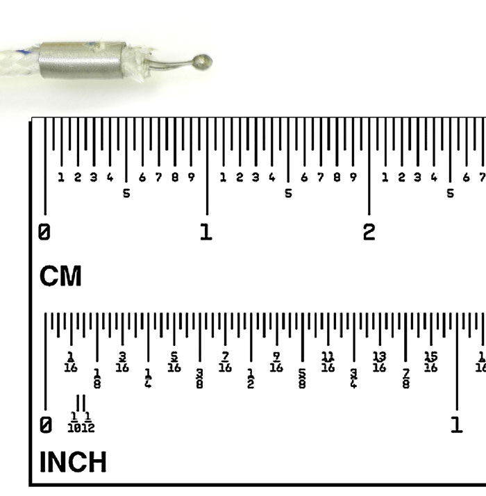
Measuring Temperature
Temperature Measurement for Outdoor:
Set the function switch to the green "0.1°C" position or "1°C" position.
Then the display will show the environment temperature reading value °C directly.
Insert the black plug of temperature probe the COM jack and red plug to the "V/Hz%/Ω/Cap/°C" jack.
Touch the end of the temperature sensor to the area or surface of the object to be measured. The display will show the temperature reading value °C directly.